In this post I have explained a simple, compact, 220V, 120V transformerless light chaser circuit which can be used for illuminating 220 V mains operated lamps or bulbs in a sequential chasing manner.
Main Technical Features
The chasing or running lamp effect can be altered by means of pot controls. The system can be used as a decorative lighting during festive seasons like in Christmas and Diwali. The idea was requested by Mr. Ashish.
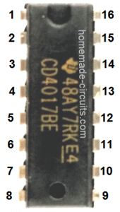
As usual, the proposed Diwali, Christmas light chaser circuit is built around the ubiquitous IC 4017 which is a divide by 10 Johnsons counter/divider IC.
It basically has 10 outputs in the order 3, 2, 4, 7, 1, 10, 5, 6, 9, 10 pinouts which can be made to shift in a sequential manner, one after the other by providing voltage pulses at its pin#14.
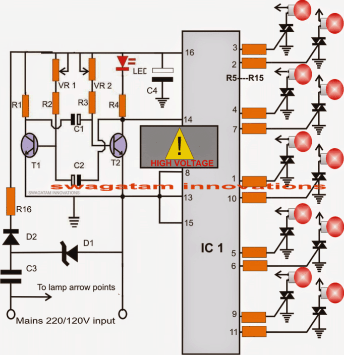
The above outputs can be either connected with LEDs for acquiring an illuminated chasing effect or can be terminated with triacs for driving 220 V mains operated lamps or incandescent bulbs in the same fashion, as shown in the diagram below.
Referring to the circuit diagram, we can see that the IC1 is clocked or pulsed at its pin#14 through a transistorized AMV stage.
Circuit Operation
This transistor astable multivibrator produces alternate high and low pulses at the collectors which can be witnessed by the blinking red LED.
With every high pulse or blink of the red LED, the output of IC1 sequences to the next subsequent output pin and continues to do this with every subsequent pulses at pin#14.
When the output reaches pin#11, the IC resets and the sequence returns to pin#3 for commencing a new cycle.
Here, since the outputs are terminated to gates of triacs, the triacs conduct with the same sequence illuminating the connected AC lamps producing a running or chasing effect.
The speed of this chasing or sequencing can be altered by simply adjusting the two pots VR1, VR2 appropriately.
The circuit runs from direct mains through a capacitive power supply and is therefore not isolated from lethal mains current, observe extreme caution while testing/handling the circuit while it's in an uncovered position.
Circuit Diagram
CAUTION: NO MAINS ISOLATION PRESENT....HANDLE WITH EXTREME CAUTION TO AVOID SHOCKS, AND FATALITY.
Parts List
- R1, R2, R3, R4, R5----R15: 1K
- VR1, VR2 = 100k
- C1, C2 = 10uF/25V
- C3 = 474/400V
- C4 = 100uF/25V
- D1 = 12V zener, 1 watt
- D2 = 1N4007
- R16 = 10 ohms, 2 watt
- Triacs = BT136
- IC1 = 4017
- T1,T2 = BC547
- LED = red, 5mm
220 V Lamp Chaser using IC 7413
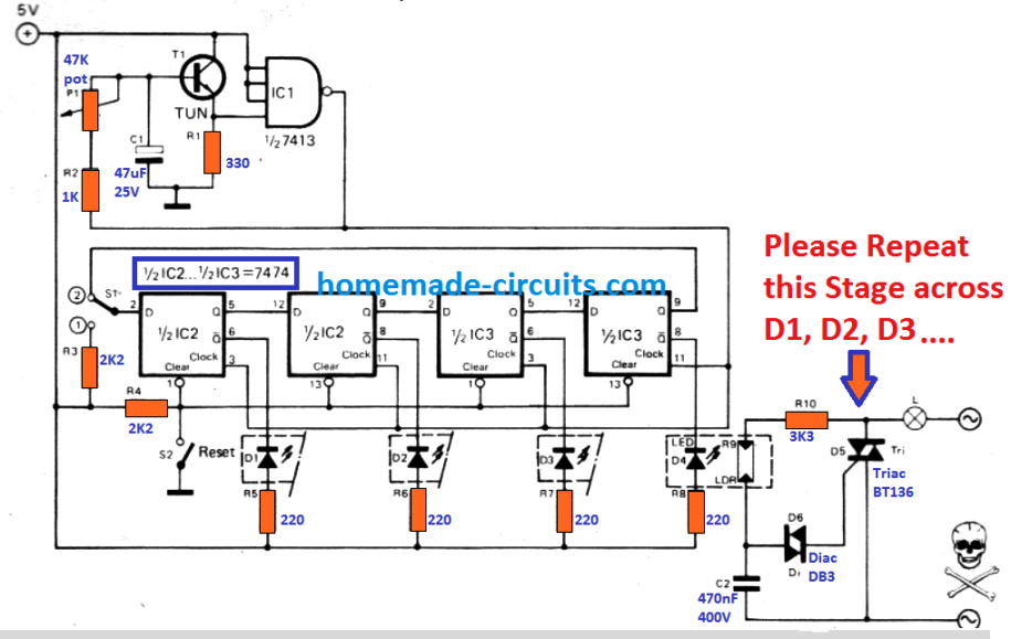
Through this circuit four 220V lamps could be used to illuminate in sequence, such that a 'running-light' effect is generated. The circuit is made up of square-wave generator (T1 , IC1), a shift register (IC2, IC3), and the lamp driver stages. P1 is used to vary the frequency of the square-wave from 0.1 Hz to about 10 Hz. The square-wave voltage is supplied to the clock inputs of the shift register.
When S2 is pressed the flip-flops get reset. The Q-outputs then turn into '0' and the Q-outputs into '1', all LED's are shut off and all the lamps are switched OFF. When S2 is released, S1 comes in position 1 causing the input of the register toturn into logic '1'.
Following one clock pulse, the input data of the flip-flop is carried to the output which illuminates the first lamp; S1 is now gets reset to position 2. From here on every subsequent clock pulse shifts the logic '1' on to the next flip-flop which in turn resets the last one, which causes the lamps to light up in sequence, producing a four 220V lamp chasing effect.
220V LED Chasing Lamp for Christmas and Diwali
The following design shows how a beautiful looking solid state LED light chaser can be created that will work directly from a 220V or 120V AC outlet.
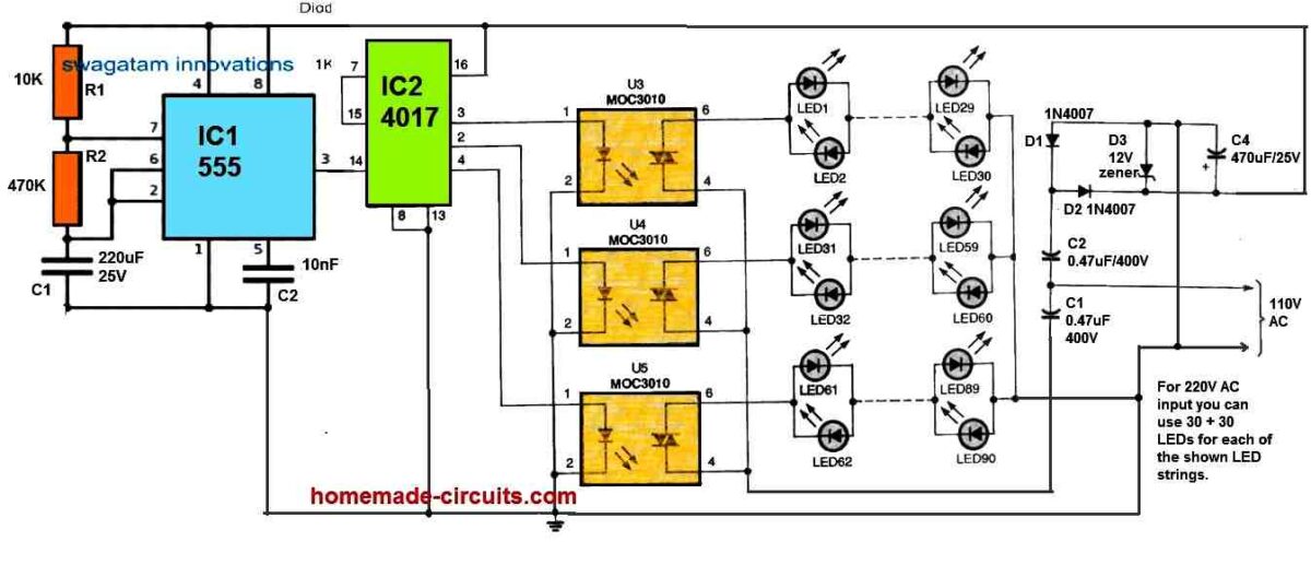
In this circuit, the IC 555 feeds a train of pulses at 0.5 Hz to the clock input of the IC 4017.
The IC 4017 responds to these pulses and outputs a shifting high logic sequence across its 3, 2, 4 pinouts to power the connected opto coupler sequentially.
The opto coupler outputs can be seen configured with strings of LED lamps which illuminate sequentially in response to the opto coupler conduction, directly from a 220V AC input through a transformerless power supply.
The MOC 3021 ICs actually include a zero crossing detector, to eliminate the mains AC current surge on the LEDs. This ensures that the LEDs never burn due to sudden current surge.
The opto couplers also ensure that while sequencing the switching action does not generate RF noise.
This simple transformerless LED chaser circuit can be effectively used for creating decorative LED string lights during festivals like Diwali and Christmas.
The sequencing rate can be changed by altering the value of the 220uF capacitor associated with the 555 IC.


Comments
how many bulb can i use in this circuit? in series and parallel
depending on the triac rating you can add more bulbs in parallel on each string
What is lec in circuit?
It's the LED
How Can we increase the no. of leds
the above circuit is for 220v mains bulbs, not leds.
actullly i am a 12 small kid. once i went to a temple and saw a running light
LEDs in that was just getting on and of then i thought it would be a multi wave ocillator circuit which have heavy duty transistors and is switching even and odd number LEDs that were creating a running effect can i make a running light like that for diwali decoration?
Hi Nobert,
yes you can do it, use 8050 transistors, it will be enough for handling the leds in parallel, also include resistors for each LED string
No sir actually i observed that the LEDs placed in odd number places and LEDs placed on even number places were acting as the two loads in a disco light circuit i am having which i got from Bal Bhavan,Delhi it contains two transistors switching two loads in the runing light i saw in temple the two loads were even number and odd number LEDs connected in parallel connection so can i use that circuit by using two high power transistors?
i'll try to find this circuit for you, and inform you if i find it.
hi bro
can i connect low power leds at the outputs of decade counter ? any modification should be made in the power supply ?
yes you can connect leds at the outputs of the IC..no mods required.