Due to some reason if the loudspeaker of a power amplifier gets shorted, that may lead to a fatal damage to the amplifier component. To prevent this an amplifier short circuit protector circuit can be very useful.
In the following post I have explained 2 simple amplifier short circuit or overload protection circuits for safeguarding amplifiers from burning.
Why we need a Short Circuit Protection
While working with high power amplifier designs, two things become crucial, the protection of the amplifier and the protection of the speakers from an accidental over current influx.
Especially when the amplifier design involves costly mosfets, the design becomes specifically vulnerable to short circuits at the outputs. A short circuit at the output may be caused due to mishandling or ignorance from the part of the user.
Whatever might be the reason, the end results in the destruction of the precious MOSFETs inside the amplifier box.
The above mishap can be prevented by adding a small circuit for detecting a short circuit conditions at the outputs of an amplifier.
Circuit Operation
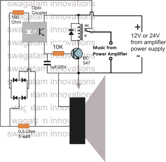
The given amplifier short/overload protection circuit diagram, shows an inexpensive design using just a single transistor for implementing the intended feature.
Normally a low value resistor is usually employed at the output of mosfet amplifiers, the current developed across this resistor can be well exploited for tripping a relay in case it exceeds the safe maximum current value.
The current threshold across the above resistor is sensed by an LED inside an optocoupler, which lights up the moment a short or overload conditions is sensed.
This instantly triggers the opto transistor which in turn switches ON the transistor driver and the associated relay mechanism.
Since the relay coils support the amplifier connection with the speaker output, disconnects the amplifier from the output connection, preventing the amplifier devices from a possible damage.
The capacitor at the base of the transistor keeps the transistor switched for a few seconds so that the relay does not oscillate randomly.
The efficacy of the above can be further increased, if the relay driver transistor is replaced by an SCR as shown below:
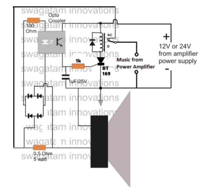
To get the pinout details of BT169, you can refer to this article.
The next simple short circuit and overload protector design presented here can be used for protecting valuable mains operated gadgets like amplifiers, TV sets, DVD players or any other similar appliance. The circuit was requested by Mr. Ashish.
Technical Specifications:
I really found very very useful circuits in your blog and I have tried most of it , Thanks for that .
I have made a 150 Watt Mosfet Stereo Amplifier and I was searching for a good, simple short circuit protection circuit for this amp , I only found protection circuit for speakers in your blog and I have added it .
I wanted a simple low cost Short circuit protection circuit after the rectification stage to protect sensitive Mosfets and costly transformer . I thought you would help , Thank you
My amplifier runs at +/- 36 V and I really needed it as I live near a village where there is lot of Power problems . Can you help ????
The Design
Normally all sophisticated gadgets today incorporate an in built short circuit protector arrangement, yet still adding a more comprehensive external protection device could only benefit the connected system.
Moreover, for gadgets such as amplifiers which are home built this protection device could prove to be very effective and useful. Also for an hobbyist who prefers building electronic gadgets at home could be greatly benefited with the present idea.
The presented short circuit protector design works on a very basic principle and costs not more than a couple of dollars.
I have explained the functioning details of the proposed circuit.
On applying power, the high current from the 220V input is dropped sufficiently by C1, rectified by D1 and filtered by C2 to feed the gate of the triac T1.
The triac conducts and switches ON the connected transformer primary thus switching ON the load which in this case is a power amplifier.
The transistor Q1 along with R1, R2 forms a current sensor stage.
R2 specifically is chosen such that it develops adequate voltage across itself at the specified dangerous high current threshold.
As usual the formula for determining R2 = 0.6/current(A)
As soon as the triggering voltage accumulates across R2, Q1 activates and sinks the gate voltage of the triac to ground making it switch off.
The regulation continues as long as the short or overload condition is not removed.
The above short circuit regulation ensures that the current level above the specified dangerous level is restricted safeguarding the precious devices associated with the connected amplifier.
If a latching feature is required for the above design, the emitter Q1 can be configured with an SCR and the SCR can be used for latching and switching off the triac.
Circuit Diagram
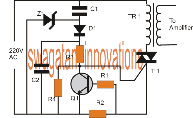
Parts List
- R1 = 100 ohms
- R2 = see text
- R3 = 1k
- R4 = 10k
- C1 = 0.33/400V
- C2 = 1uf/250V
- Q1 = BC547
- Z1 = 12V/1 watt zener diode
- T1 = BT136 or as per current rating
- TR1 = As per load requirement specs.
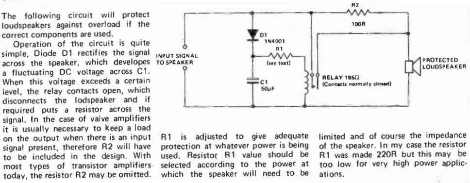
Relay Delay Loudspeaker Protection
Another simplified version of a relay delay timer for protection the loudspeaker from initial switch ON surge can eb seen in the following diagram:


Comments
Thank g
What is number of diodes
use 1N4007
This circuit is new it OK can we use in4148 diode
Thank you sir so I want to ready 6 circuit for 5.1 amplifier
you are welcome, yes that's right!
Sorry I can't understand which voltage
Input to transformer is 220 volt and the output of the transformer is 24 volt the transformer current rateing is 5 amps
Mean while I get only 1 ohmes in India
Thank-you
the 0.5 ohm shown in the diagram will need to be calculated as explained using the formula in the previous comment.
If your amplifier operating volatge is 24V then
100/24 = 4.16
R = 1.5/4.16 = 0.36 ohms
wattage of resistor will be = 1.5 x 4.16 = 6.24 or a 10 watt will do.
if you are getting 1 ohm then use two in parallel, in place of the indicated 0.5 ohm
…..two 1 ohm in parallel will do in place of 0.36 ohm
100 Watts 5.1 amplifier system it is designed by MOSFET IC I have changed my speaker for more than 8 times in 2 years
Thankyou
for 100 watt you can use the following formula
100/V = current
therefore R = 1.5/current
here V is your amp supply voltage
Can I use MCT2E instead of 4N35
yes you can!
Sir thank you for reply but in India only 1 omhs is available can I use that one
Thanks again
saravanan, please tell what is the max wattage limit do you prefer to implement? the resistor value will depend on this
Say the value of resistance 0.5 ohm iam not able to get in india
use 5nos of 0.1 in parallel
OK it is useful circuit I want to know the number of opto couple
Thank-you
use 4n35 optocoupler
Useful but I want the number of opto couple
thank,,, its usefull
not tested, but i am sure about it.
yes it would also handle DC shorts across the speaker
Hi,
yes by mistake the positive connection is not shown in the diagram, a separate +12V should be connected to the link that connects the relay coil and the opto transistor.