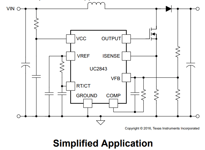
This UC2842 IC based SMPS design is simple, cheap and efficient kind of isolated power supply. We can use it in off-line stuff like AC-DC adapters, battery chargers and all those small power supplies. What is cool? It takes that high voltage AC then steps it down and then keeps input and output fully isolated for safety. So we pick UC2842 IC for this job because it works great, easy to use and real tough.
Basic Working
So this thing works by storing and dumping energy. Different to other converters that just pass power through a transformer, this one first stores energy in the core when the switch is ON and when it turns OFF then it throws all that stored energy to the output.
What Happens Step by Step?
Mains AC Comes In, Gets Rectified and Filtered:
We got mains AC, right? It goes through a bridge rectifier, then gets turned into DC and then a big capacitor smooths it out.
The DC voltage after rectification:
VDC = √(2) * VAC - Vdiode
So if we got 230V AC, then this thing gives us roughly 325V DC.
Switching and Energy Storing:
UC2842 drives a MOSFET switch (let’s say IRF840 for 230V mains) at some high frequency, like 50-100 kHz.
When MOSFET is ON then current flows in the primary winding of the transformer and subsequently energy gets stored in the magnetic core.
Energy Release and Output Rectification:
MOSFET turns OFF and now all that stored energy jumps to the secondary side.
There is a fast diode (UF4007, MUR460, etc.) that rectifies it and a capacitor smooths it out.
Now we got a stable DC output ready for use.
Feedback Control and Voltage Regulation:
We sense the output voltage using an optocoupler and a TL431 regulator.
The UC2842 adjusts its duty cycle to keep output voltage steady.
What Parts We Need?
Main Stuff in the Circuit:
- UC2842 PWM IC – Runs the whole show, switching the MOSFET.
- MOSFET – (Like IRF840) Switches the transformer on and off.
- Flyback Transformer – Custom-wound, step-down voltage.
- Fast Diode – (UF4007, MUR460, etc.) Blocks reverse voltage.
- Output Capacitor – Stores charge, filters output.
- Snubber Circuit – Stops high-voltage spikes on MOSFET.
- Optocoupler (PC817) – Isolates and sends feedback.
- TL431 – Controls feedback voltage.
Detailed Working
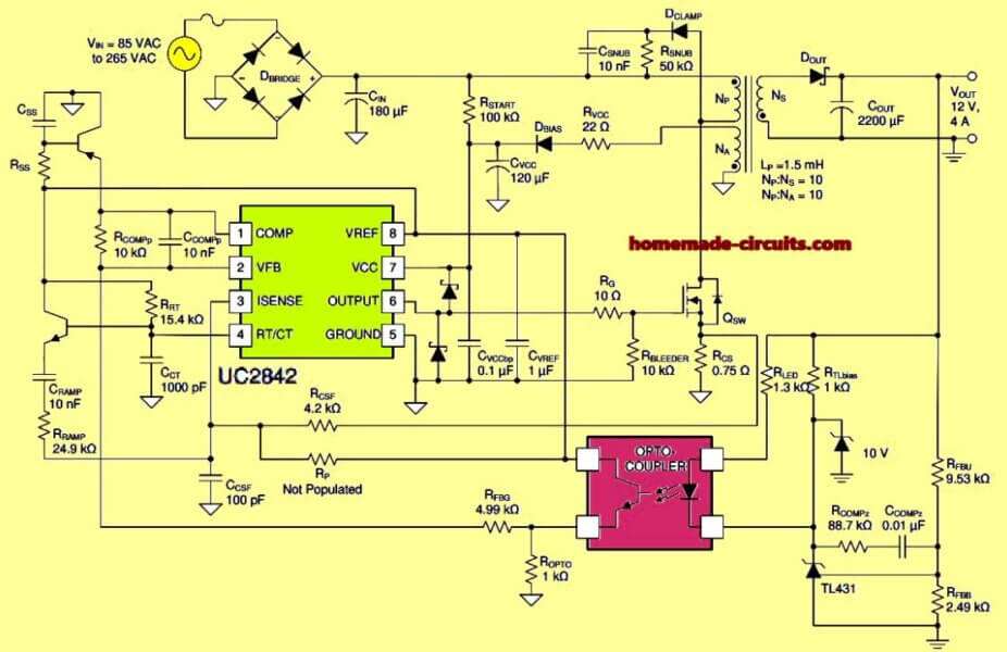
Now referring to the UC2842 220V to 12V SMPS converter circuit diagram, it takes 85V to 265V AC, converts it to 12V DC at 4A. This is a wide-input isolated power supply, meaning the input and output are fully separated by the transformer. It’s perfect for adapters, battery chargers, and low-power SMPS.
So let us see what is happening in the circuit step by step.
AC to DC Rectification and Filtering
First we got AC mains (85V to 265V).
This goes into a bridge rectifier (D_BRIDGE) which converts AC into pulsating DC.
Then a big capacitor (C_IN, 180µF) smooths it out and gives us DC voltage (somewhere between 120V DC to 375V DC with regards on input AC voltage).
Formula for DC voltage after rectification:
V_DC = √(2) × V_AC - V_diode
For 230V AC, we get 325V DC.
Powering the UC2842 IC
The UC2842 needs around 10V to 30V to run.
It gets power through R_START (100kΩ) which drops the voltage from the high-voltage DC.
Then there is D_BIAS (diode) and C_VCC (120µF) which keeps the voltage stable at VCC pin (pin 7).
Once UC2842 starts switching, then it self-powers using auxiliary winding N_A.
Flyback Transformer Action
This transformer is the main part here.
It has three windings:
Primary winding (N_P) - Connected to MOSFET drain.
Auxiliary winding (N_A) - Powers UC2842 after startup.
Secondary winding (N_S) - Provides 12V output.
When the MOSFET (Q_SW) turns ON then current flows through N_P winding and energy gets stored in the core.
When the MOSFET turns OFF then this stored energy is pushed in to the secondary winding (N_S) and here it gets rectified by D_OUT.
Transformer Ratios:
N_P : N_S = 10:1
N_P : N_A = 10:1
This means that the secondary voltage is about 12V and auxiliary winding voltage is enough to keep UC2842 running.
Feedback and Regulation
The output voltage (12V DC) is sensed by a TL431 programmable reference.
It adjusts the current through an optocoupler which sends feedback to UC2842's VFB pin (pin 2).
The UC2842 adjusts the duty cycle of the MOSFET to keep output voltage stable.
MOSFET Switching and Protection
The MOSFET (Q_SW) does the switching at a high frequency (~50-100kHz).
A gate resistor (R_G 10Ω) controls the gate drive current.
Snubber network (D_CLAMP, C_SNUB, R_SNUB) absorbs most of the voltage spikes to protect the MOSFET.
A current sensing resistor (R_CS, 0.75Ω) is used to limit peak current to prevent damage.
Formula for peak current limit:
I_peak = 1V / R_CS
Here, R_CS = 0.75Ω, so I_peak ≈ 1.33A.
Output Rectification and Filtering
Once energy moves to the secondary winding (N_S) then it goes through D_OUT which is a fast recovery diode.
C_OUT (2200µF) smoothens out the ripples, giving us a steady 12V DC.
R_LED and R_TLbias helps to control the TL431.
Output ripple voltage formula:
V_ripple = (I_out × D_max) / (f_sw × C_out)
Safety and Isolation
The optocoupler (PC817 or equivalent) ensures that there is no direct connection between the high-voltage side and low-voltage side.
The snubber circuit protects the IC against voltage spikes.
The feedback loop with TL431 ensures that the output remains stable and regulated.
How We Calculate Everything
Power Calculation:
Output Power:
Pout = Vout * Iout
Input Power (Including Losses):
Pin = Pout / efficiency (eta)
Efficiency is around 75-85% usually.
Primary Side Stuff:
DC Voltage After Rectifier:
VDC = √(2) * VAC - Vdiode For 230V AC, we get 325V DC.
Primary Current:
Iprimary = (2 * Pin) / (VDC * Dmax)Dmax is usually 50-60%.
Transformer Winding Calculation:
Turns Ratio:
Npri / Nsec = (VDC * Dmax) / (Vout + Vdiode)
Primary Inductance:
Lprimary = (VDC * Dmax * Ts) / IprimaryTs
= 1 / fsw (fsw is switching frequency).
Output Capacitor Sizing:
Capacitor Value Based on Ripple Voltage:
Cout = (Iout * Dmax) / (fsw * Vripple)
Snubber Circuit to Protect MOSFET:
Snubber Resistor:
Rsnubber = (Vpeak^2) / Psnubber
Snubber Capacitor:
Csnubber = Ipeak / (dV/dt)
How to Build and Test This UC2842 220V to 12V SMPS
PCB Design Rules:
Keep high-current tracks short and thick.
Put UC2842 close to MOSFET to avoid noise.
Route high-frequency paths properly.
Transformer Winding Tips:
Use good insulation and wind primary first, then secondary.
Keep tight coupling for good efficiency.
Use ferrite core with high permeability.
Heat Management and Protection:
Use a heatsink on MOSFET and output diode.
Put current sensing resistor to avoid overload.
Keep good isolation between high-voltage and low-voltage areas.
How to Test the Circuit:
- Power it Slowly – Use a variac and start with low AC voltage.
- Check Drain Voltage – Look at MOSFET waveforms.
- Adjust Feedback – Make sure the output is steady.
- Thermal Testing – Load it fully and check heating.
- Final Tweaks – Tune snubber and compensation network for best efficiency.
Conclusion
So yeah this UC2842 flyback 220V to 12V SMPS converter circuit is simple but powerful. If we pick the right transformer, feedback circuit and snubber then this thing works rock solid. Just follow these steps, check all values, and we can build a safe, efficient, and long-lasting flyback power supply.
Source:


Comments
any evaluation board available please give reference ?
I tried to find it online, but it seems it is not yet designed by the manufacturer…
pls do have any clue about this ic sc2583T and it replacement
thanks
I have not yet studied this IC, so I am not sure right now…
pls what is the value of the transistors and zener diode and can I use a chopper transformer from another smps without rewinding it in this circuit like
19 volt chopper transformer
Okon, which circuit are you referring to?
smps ic 2842 circuit
Customizing a UC2842 as per your chopper transformer can be difficult, instead you can use some other half bridge ICs as suggested below:
https://www.homemade-circuits.com/?s=IR21
can you please help me with a swich mofer power supply circuit profucing 5VDC f@ 500mA. Vin is 20V + or minus 4 V AC built from first principles and no chip solution . also volatge should be regulated as well as overcurrent or short circuit protection.
I think you can modify the following concept to suit your specific application requirements:
https://www.homemade-circuits.com/0-300v-variable-voltage-current/