I have posted many battery charger circuits in this site, some are easy to build but less efficient, while some are too sophisticated involving complex construction steps. The one posted here is possibly the easiset with its concept and also is extremely easy to build. In fact if you had all the required material you would build it within 15 minutes of time.
Introduction
The concept is indeed hugely simple and therefore pretty crude with its going. This means that though this idea is too simple, would require appropriate monitoring of the charging conditions of the battery, so that it does not get over charged or damaged.
Materials Required
To make this simplest battery charger circuit quickly, you would require the following bill of materials:
- One rectifier diode, 1N5402
- An incandescent bulb, having voltage rating equal to the battery which needs to be charged and current rating close to 1/10th of the battery AH.
- A transformer having voltage rating equal to twice that of the battery voltage and current twice the charging rate of the battery. That means if the battery is 12V, the transformer should be 24V, and if the AH of the battery is 7.5 then dividing this by 10 gives 750mA which becomes the recommended charging rate of the battery, multiplying this by 2 gives 1.5Amps, so this becomes the required current rating of the transformer.
Building this Simplest Charger Circuit
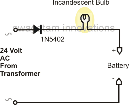
After you have collected all the above material, you may simply connect the above parameters together with the help of the diagram.
The functioning of the circuit may be explained in the following manner:
When the power is switched ON, the 1N5402 diode rectifies the 24V DC to produce half wave 24V DC at the output.
Though the RMS value of this voltage may appear to be 12V, the peak voltage is still 24V, therefore it cannot be applied directly to the battery.
To blunt of this peak value, we introduce a bulb in series with the circuit. The bulb absorbs the high peak values of the voltage and provides a relatively controlled output to the battery, which becomes self regulatory through the glow of the filament intensity of the bulb (varying resistance).
The voltage and current thus automatically becomes adjusted to appropriate charging levels which becomes just suitable for the battery safe charging.
The charging of the battery can be witnessed by the gradual dimming of the bulb as the threshold charging voltage of the battery is reached.
However once the battery voltage reaches close to 14.5V, the charging must be stopped, irrespective of the bulb glow condition.
Circuit Diagram
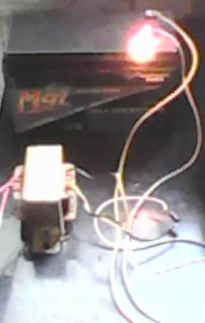
Video Clip showing the charging process using a single diode:


Questions & Answers
Hello Sir,
What type of battery charger u r discussing with mr carl carbeau in above discussion.
I had also read some where to make battery charger by simple ac run capacitor and by diode bridge.is it fisiable and safe to charge high ah rating battery with this charger.i had also read that it also helps in desulphating the battery as u where also discussed above.
Yes it can be done, but the whole wiring becomes risky and the terminals of the battery float at the mains potential, the whole thing becomes very dangerous to touch.
Thanks for ur reply sir,
Will u give me some idea of components i had to use for 12v 9.4ah amp battery. actually i want to desulphate this baterry.
And how would i know that my battery is charged
Thanks
If you are referring to the above circuit then you may try a 24V/5amp transformer and a 12V automotive headlamp.
Keep an ammeter connected in series with the supply, it should indicate gradual increase in the current consumption, and subsequently a gradual decrease in consumption, until zero.
Thanks sir,
Will ur above circuit is able to desulphate batteries
Can i use 12-0-12 trafo by connecting 12-12 tap together
I am not sure, but since it generates pulsed DC at 50Hz can be tried for the purpose.
And can i use 12-12 tap together to get 24v from 12-0-12 trafo
yes you can do it.
Thanks sir
hello sir,
can u please teach me how to use 12-0-12 transformer to get 0-24 for above circuit.
will i have to connect 12-12 tap directly for 24
or via diodes
->can a bridge "D25SBA80" should be used as bridge rectifire in a 150ah battery charging circuit.as it is rated to handle 25 amp current according to its datasheet.(not related to above circuit)
hello avijeet,
for the above circuit you will need only one diode as shown and you can connect 12-12 tap for getting 24V.
yes a 25amp diode bridge can be used for 150ah battery charging.
no, this circuit is not applicable for small batteries.
connect the 4V source directly with your phone battery (3.7V) and remove it as soon as the phone battery reaches 4V.
the source current supply must not be more than the cell phone battery AH rating.
Hello sir,
I ant to design a charger which can charge batteries at 10 times of rated current, for quick charging…
pls suggest some info about it.
Hello Pooran,
It will damage and destroy the battery, so it's not recommended.
Hello Gopal,
Presently I do not have a multi-charger circuit for 180AH battery, I'll try to design it if possible, and let you know.
Dear Sir,
How to read this design. Is it like the current first comes to transformer then diode then bulb and then battery? Can I use this same way to charge a battery through power produced by mini wind turbine?
Thank you,
Rahul
Dear Rahul,
yes you can read it in that way.
With a wind generator you would need a voltage regulator circuit also because the supply from a wind generator could vary a lot.
how can i make a battery charger?with the help of this b.c.how can i charge different types of battery like cellphones battery or cars battery?can it possible?
this circuit cannot be used for charging all types of batteries, for cel phone batteries you will need more complex designed as already explaimed in many of the posts in this blog
Sir.. Where can i find rectifier diode 1N5402. Can i find that in an old appliances?
Sir.. Can i use another diode if i have not that one? And what diode can i use?
John, you can get it from any 3amp/5amp power supply box or a power amplifier circuit etc.
you can also try making it by putting two or three 1N4007 diodes in parallel.
Welldone sir,
I want to make this but i have some question.
1. Can i use this circuit to charge an sla battery 12v, 7.2ah?
2. Is the circuit safe for charging battery? And how long will it take to charge d above battery fully?
3. Can the output be fully rectified and filtered for pure dc?
4. What adjustment can be made to give more quality ? Thanks
thanks Madamidola,
the circuit is safe but crude so will need to be switched off as soon as the 14.4V mark is reached.
yes the given specs are for charging a 12V battery
if you intend to rectify the the transformer output with a bridge network, do not use a 24V trafo, rather use a 12V trafo and a12V automotive bulb
for more quality, you may include an opamp based cut-off satge, use lm338 stage for regulation, use heat sensors etc.
…back up time is 10 hours with a 1amp trafo for a 7ah battery
sorry it's not back up time, it should be charging time in the above comment….
Thanks sir.
Can i use 12v 500milliamp transformer to charge the battery
with a 12V/500ma, use a bridge rectifier, a 2200uF/25V filter cap and simply connect the output directly to the battery, wait for 15 hours and you'll find the battery reasonably charged.
Pardon sir.
I have a 3 anodes 12v, 1.5amps, how can I use it to charge a 12v, 7.2ah battery?
How long will it take for full charge
what's 3 anodes?? please clarify
I mean 12×2 v 1.5amps transformer
use center tap and one of the outer taps, connect these with a bridge network, filter the bridge output with a 2200uF/25V cap and connect it with your battery, wait for 10 hours.
Sir the output voltage is just 10.2v
Can I still use it
you have used a bridge, or a single diode???
hello sir can i charge 4v 2.5Ah sla battery with mobile phone charger??
yes you can do it
Which transformer rating is used if i want to make 12V, 180Ah Battery Charger?
12V….25 amp
sorry 24V /25 amp
I have a UPS that doesn't work anymore.
But there is a transformer inside it.
And I have a car battery too, 25Ah.
I have another UPS that works well but is not enough to charge this battery.
How can I use the working UPS and the battery with the components of the older UPS to get an inverter kind of thing?
you can look for the parts inside the bad UPS that's indicated in the second diagram of the following link, and use them to make the shown automatic battery charger circuit
https://www.homemade-circuits.com/2011/12/how-to-make-simple-low-battery-voltage.html
Sir, I have adapter 19V 3,5A, how to step down Voltage to 14V and Current to 1A?
you can use an LM317 voltage regulator circuit for implementing it.
I tried use LM 317 T, but failed 🙁
What LM 317 and LM 317 T are different?
please do it as shown in this diagram:
https://www.homemade-circuits.com/2012/02/how-to-make-current-controlled-12-volt.html
LM317 T should also work
will try to publish it soon…thanks
Thanks Danang, I am glad it worked for you as proposed in the article.
but instead of using parallel 1N4007 diodes, you must use a single 1N5408..or put 1 ohm 1watt resistors in series with each of the 1N4007 diodes
Dear instructor, my name is Otunba Richard Olaniyi-Oshin from Nigeria. I'm a Mathematician but I am in love with constructing simple appliances that could solve modern day problems. I have been searching for a simple battery charger that could charge my 12volts 200amps batteries because my inverter didn't come with an inbuilt battery charger; thanks for the simple diagram above. I have read that all I need are 12v transformer, diode and battery terminal clips. Sir, my question is, how do I connect the diode to the transformer? Is it to any of the 2 wires of the 12v transformer. Pls, enlighten me. Thanks for solving our problems! God bless you.
Dear Richard,
the above charger will charge your battery but it will not switch OFF after the battery has reached full charge, therefore you may have to monitor it with a voltmeter, and switch it OFF once charged fully.
the diode can be connected to wire, it's not critical…..but the transformer will need to be rated at 20 amp 15V minimum