In this post I have explained how to make a LED string light which can be operated from 220V mains through a single inexpensive PPC capacitor. The idea was requested by Mr. Basit Momin.
WE STRICTLY CAUTION YOU THAT YOU BUILD THIS CIRCUIT ONLY IF YOU ARE AWARE OF THE DANGERS OF MAINS AC AND KNOW HOW TO MAINTAIN EXTREME SAFETY AGAINST IT.
REMEMBER, THE CIRCUITS EXPLAINED BELOW IS NOT ISOLATED FROM MAINS AC AND CAN INFLICT LETHAL ELECTRIC SHOCK IF ANY EXPOSED PORTION OF THE CIRCUIT IS TOUCHED IN POWERED CONDITION, SO MAKE SURE THAT THE FINAL STRING LIGHT ASSEMBLY IS PERFECTLY INSULATED WITH PROPER PLASTIC COVERS AND CAPS.
Technical Specifications
I am trying to make AC 1 watt led bulb like 6.2 v 3 amp miniature lamp or festival decoration lamp so it will be easy to solder led without seeing plus and minus of leds , so it will be easy to solder led in series without seeing plus and minus of led so pleas help
Actually I want to make 100 nos of led toran of 2 array each array of 50 leds I am trying to convert leds in AC bulbs like 6.2 v festival decoration lamps so that's my question sir
Can we run the LEDs without the circuit by adding some ics to each led. I want to run it direct on 230v AC without any circuit like festival series lamps.
Basit Momin
Analyzing the Circuit Request
Hello Basit,
LEDs are different from filament bulbs and are much vulnerable to current fluctuations, without a dropping capacitor the LEDs will start blowing off with the slightest voltage fluctuations if connected directly or through resistors.
Therefore a recommended capacitive power supply circuit has to be used with it.
Basit: So we cannot make AC led Series bulbs ?
Solving the Circuit Issue
You'll have to include the high voltage isolating capacitor, rest of the components can be eliminated.
make two 50 LED series and connect their opposite ends together, meaning the anode end of one series should be connected with the cathode end of the other series in both the ends.
Now simply connect one end of this assembly to one of the mains terminals while the other to the other mains terminal through a high voltage capacitor.
The whole set up will be too dangerous to touch, exercise adequate caution.
The Circuit Diagrams
Testing the above LED string light design using a single PPC capacitor:
The idea looks simple and feasible and also quite reliable due to the large number of LEDs in series taking care of the initial surge current.
The large number of LEDs makes sure that the total LED forward drop is close to the AC mains value which enables restricting the initial current to a reasonable level.
If we assume the forward drop of the shown white LEDs to be around 3.3V, then with 50 LEDs in series it gets to approximately 3.3 x 50 = 165V, though not too close to 220V but sufficient enough to just counter the initial surge from the PPC capacitor which acts like a momentary short circuit each time power is switched ON.
Probably 90 numbers would be just adequate and perfectly safe.
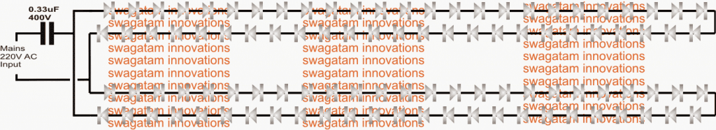
As can be seen in the above diagram, there are 50 LEDs on the upper string joined in series and an identical string with an identical number of LEDs at the lower side of the design.
The free ends of these two series are connected to each other but using the opposite polarities, that is the anode side of one string is made common with the cathode side of the other string and vice versa.
The mains AC is applied to these common joints through a PPC high voltage capacitor.
A nominal 0.33uF is shown in the diagram assuming that 5mm LEDs are used in the circuit.
We know that mains AC is fundamentally composed of alternating current which changes its cycle polarity 50 times a second, constituting the 50 Hz spec.
The LED strings are deliberately connected with their opposite end polarity so that one string illuminates in response of one half AC cycle while the other string for the other opposite AC half cycle.
Since this is supposed to happens very quickly (50 times per second) the human eye is unable to distinguish the fractional lapse or shutting off of the strings, and both the strings appear to be lit up brightly and continuously.
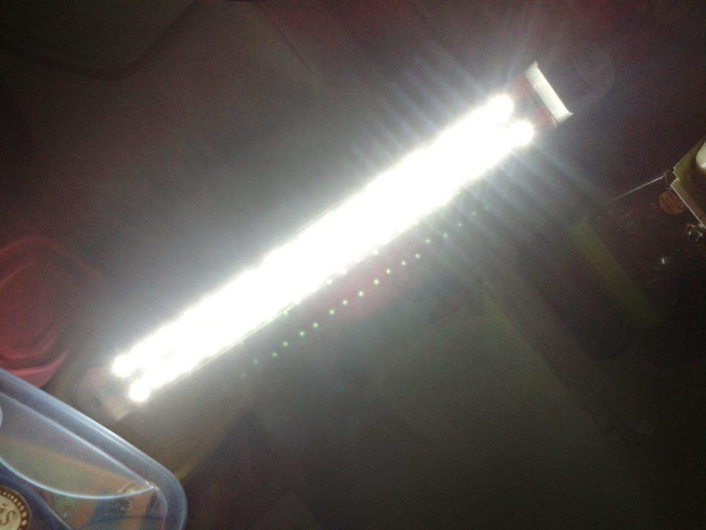
The above design was successfully built and tried by Mr. Ram, the following picture provides a dazzling performance proof for the same.
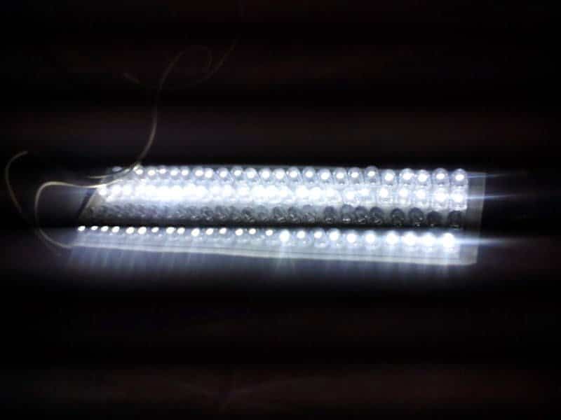
The circuit was also built and tested by Mr. Raj, who is also an avid follower of this blog, the picture below was sent by him for the readers viewing pleasure.
Another LED String Light using a Single Capacitor
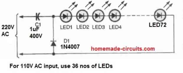
Our first LED light string includes 72 LEDs linked in series, as seen in the accompanying image. The capacitor and the diode should be placed in an insulated container, while the LEDs must be contained in a piece of transparent pvc pipe.
You could wish to use small bits of small-gauge, shielded, thin wire between the LEDs to spread them out throughout the length of the tube.
The circuit works as simply as it possibly can.
1uF 400 volt capacitor C1, which is linked in series with the LED string, serves as a no-loss, AC current-limiting element of the circuit.
The reactance of the capacitor behaves just like a resistor to the AC current without incurring the losses associated with a typical power resistor. The 1N4007 silicon diode shields the LEDs from harm caused by reverse voltage.
All the LEDs can be 5mm, 20 mA high bright white LEDs.


Comments
Sir then wat will be the capacitor for 5mm leds if I connect 3 capacitor in parallel for 5mm leds it will be correct for that
you can use 334 or 474 (0.47uF) for 5mm or 8mm LEDs
Sir i have polyester film capacitor of value 1uf 400v can I add 3 nos of capacitor in parallel for this circuit
Sir i have polyester film capacitor of value 1uf 400v can I add 3 capacitor parallel and run for this circuit
334 = 0.33uF…. 3nos 1uF in parallel = 3uF that's 10 times bigger than than 0.33u
you can use 334 or 474 (0.47uF) for 5mm or 8mm LEDs
For 5mm leds and 8mm leds
So sir i have to connect one single polyester capacitor of value 334 400v
for 1 watt LeDs, it would be just OK to connect 3nos 1uF in parallel, it would constitute an equivalent of 3uF (210mA)
Ok
So sir wat will be the input capacitor for 1watt and 8mm led
5uF/400V….. but you must include 50+ LEDs in series as mentioned previously, 90 is most preferable for 220V, and 45nos for 120V
Thanks so much for making this circuit thanks a lot….. And can I use 1watt and 8mm led for it
you are welcome Basit, yes all types of LEDs can be used, but the input capacitor will need to be upgraded accordingly.
also at least 50 or above quantity is recommended (@220V) for preventing surge vulnerability.
Got it working with 334 /400. I connected all 52 in series. Added NTC and MOV for extra surge protection. Thank you very much.
s16.postimg.org/rc2j6hsf9/2015_04_04_15_16_46.jpg
that's great Ram, thanks very much for the update and the picture.
Sir, what will be the exact part number for 0.33uf 400v. I m unable to get if value mention in uf.
I was trying to do same and you helped me before but when I try to light up 52 led in series ( 5mm ultra bright 35ma) with 474j/400v , 474j/250v nothing happen even after using bridge rectifier. I have some ppc capicator of value like 105j/250, 475k/250v, 474k/250v. Please help how I can light up 52 led in series. if not possible easily for 52 led then I can your above mention method by dividing it in 27 n 27 and will need help to get the exact value of capacitor.
s8.postimg.org/o4l5uaf9h/2015_04_03_16_36_39.jpg
If possible also help how to know the part no if value mention in uf / volt and
calculate uf if value mention in format like 474k/25v.
Regards
Ram, the LED strip will not light up if even one LED is connected with a wrong polarity, so if all your 52 LEDs are connected with the right polarity in one direction it will surely light up.
you can use the above technique but using less number of LeDs will mean greater risk to surge current.
for 0.33uF the code will be 334