This simple mains 220 V, 110 V AC voltage home protector circuit will protect all the mains operated appliances of your home from high and low voltage situations and also from sudden voltage surge.
The circuit can be used with 220 V AC inputs and also with 110 V AC inputs.
The circuit will basically provide the following two types of protection to all your home appliances:
- Protection against high and low mains voltages.
- Protection against sudden voltage switch ON surge whenever AC mains restores after a brief voltage failure.
This circuit performs incredibly well and is highly suitable for home appliances.
Circuit Description
With reference to the following diagram, the working of the proposed AC mains home protector circuit can be understood with the help of the following points:
Parts List
- All Resistors are 1/4 watt CFR 5%
- R1, R2, R4, R5 = 10k
- R3 = 4.7k
- R6 = 22k
- P1, P2 = 10k presets.
- Capacitors
- C1, C2 = 1000uF/25V Electrolytic Capacitors
- Semiconductors
- Diodes D1, D2, D3, D4, D7 = 1N4007
- Diodes D5, D6, D8 = 1N4148
- Zener Diodes Z1, Z2 = 4.7V, 400mW
- Transistors T1, T2 = BC547
- IC op amps A1, A2 = 1/2 IC LM324, or LM358 (pinouts will change accordingly)
- Transformer TR1 = 0-12V, 500mA
- Relay = 12V SPDT 30 amp
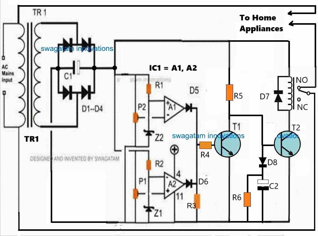
The two op amp comparators form the heart of the circuit which are configured as a window comparator for sensing the over and under voltage thresholds.
Window Comparator
A window comparator circuit is usually built using two op amps. One op amp is configured to sense the upper voltage limit threshold and the other op amp is configured to sense the lower voltage limit threshold.
Whenever the upper or the lower voltage limit thresholds are exceeded, the relevant op amp output goes high.
On the other hand as long as the voltage level stays within the safe limits, both the op amp outputs remains logic low or turned OFF.
In our home protector circuit, the upper op amp A1 is configured to sense the low voltage threshold, while the lower op amp is wired to sense the high voltage threshold.
For op amp A1, its non-inverting pin is clamped to a fixed voltage reference using a zener diode, while the inverting input is configured with a preset to sense the lower voltage threshold.
As long as the transformer DC (which is proportionate to the mains AC level) at the inverting input of A1 stays above the non-inverting pin's reference voltage, the output of A1 remains at 0V.
However, in an event when the input voltage at the inverting pin goes lower than the reference voltage at the non-inverting input, causes the output of A1 to go high.
Identically, but with an opposite function, op amp A2 utilizes a zener diode to establish a constant voltage reference at its inverting input pin, while the non-inverting input is configured with a preset to detect the high voltage threshold.
The output of A2 remains at 0V as long as the transformer DC, proportional to the mains AC level, at the non-inverting input stays below the reference voltage at the inverting input pin.
However, if the voltage at the non-inverting input rises higher than the reference voltage at the inverting input, it prompts A2's output to go high.
Thus, the two op amps makes sure that as long as the input voltage level stays within the preset "window" level, the outputs of both the op amps remains at 0V or logic low.
These voltage levels inside the comparator "window" signifies the safe limits at which our home appliances can work normally without any danger.
This safe limit, or conversely the upper and the lower unsafe cut-off limits can be appropriately adjusted and set using the P1 and P2 presets.
Transistor/Relay Switching
Now, while the mains AC voltage is within the safe limits, the outputs of the op amp remain at 0V, which keeps the transistor T1 switched OFF.
While T1 remains switched OFF, T2 remains switched ON causing the relay also to be in the switched ON position.
In this position the relay contacts are at the N/O position which allows the home AC supply to the appliances to be switched ON and working.
However, in an event when the input mains AC voltage tends to go higher or lower than the set threshold, the relevant op amp's output goes high. In either situation, T1 is switched ON.
As soon as T1 is switched ON, T2 base is grounded by T1.
This causes T2 to be switched OFF. When T2 switches OFF, it switches OFF the relay as well, causing its contacts to move towards its N/C position.
With the relay contacts shifted at N/C, the voltage supply is cut off for the home appliances, which safeguards them from the hazardous voltage situation.
Switch ON Surge Protection
The above functioning takes care of the high and low voltage correction and cut off, but what about the sudden voltage surge, during power failures and restorations?
The switch ON voltage surge is handled by the little delay ON timer configuration built using D8, C2, R6.
Whenever there is an input AC mains supply failure or interruption, C2 is fully discharged via R6.
Now, when the AC mains voltage returns, T2 and the relay are inhibited from switching ON instantly.
During this period, C2 slowly charges and keeps the base voltage of T2 below 0.6V causing it to be switched OFF, so that the relay and the home appliances also remain switched OFF.
As C2 charges slowly via R5, after some delay the voltage across C2 reaches above 0.6V which is enough to switch ON T2, relay and the appliances very softly.
This slight delayed switch ON after the mains has restored safeguards the home appliances completely from a possible hazardous switch ON voltage surge.
Calculating the Tripping Points
To setup the presets correctly we first need to confirm what levels of the DC voltages correspond to the 220V 120V AC side high and the low levels.
This can be actually quickly implemented using a variac, however since a variac may not be accessible to most of the users, we can try an alternative method through some calculations and practical testing.
Initially, keep the entire control circuit detached from the bridge rectifier.
Assuming your input AC supply is normal, switch ON the 220V or 120V to the transformer from the primary side and measure the corresponding DC output across the C1 or the bridge rectifier +/- ends.
Let's say you get a corresponding DC output of 16V. So this will be your DC equivalent of a normal 220V AC input.
Let's denote the high voltage DC tripping point as HV and the low voltage DC tripping point as LV.
We know that 220V AC corresponds to 16V DC from the above description. Let's assume the high voltage input at which the circuit is supposed to trip as 280V.
Therefore, the DC equivalent for this 280V AC high voltage can be calculated using the following cross-multiplication.
220/280 = 16/HV
HV = 20V
This 20V DC becomes the high voltage cut-off equivalent for the 280V AC side high voltage input.
Now, let's assume the low AC voltage cut off point to be 190V.
Similarly, as above, we can calculate the DC low voltage equivalent using the following cross-multiplication:
220/190 = 16/LV = 13.81V
LV = 14V
This 14V becomes the DC low voltage equivalent for the 190V AC side low voltage.
Now, since we have the high voltage and low voltage DC tripping points in hand, we can now quickly setup the presets P1, P2 through the following steps.
How to Setup
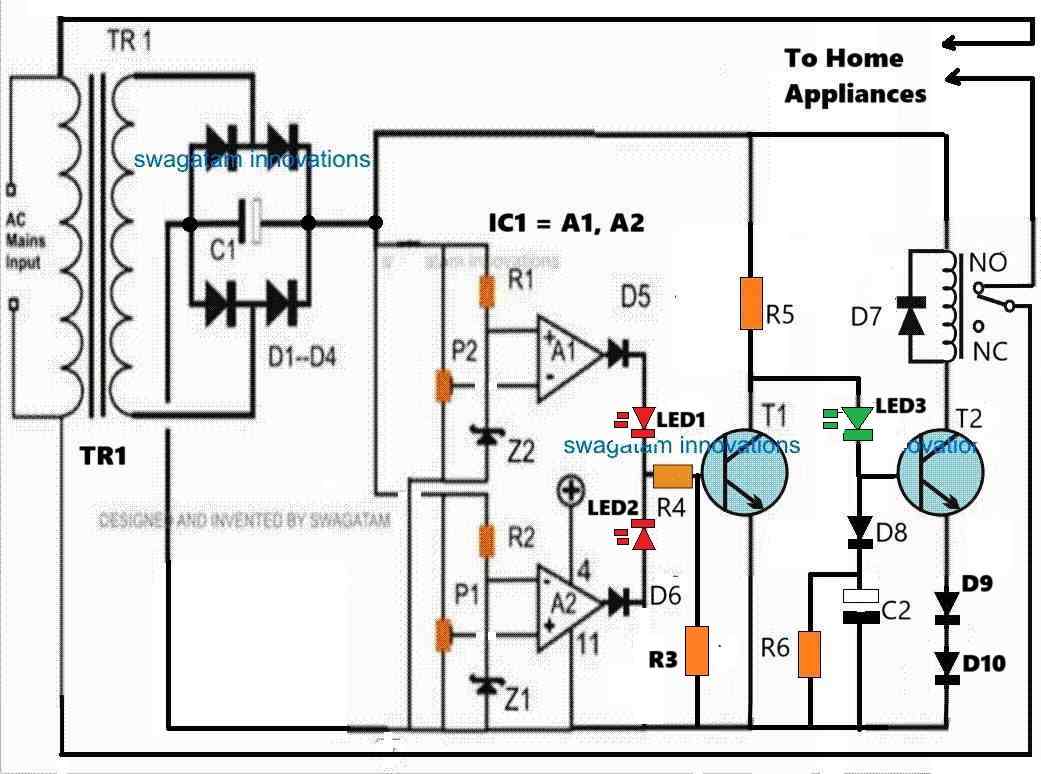
Please refer to the following modified diagram while setting up the circuit. I have improved the circuit design with a few modifications as indicated below:
I have added LED1, LED2, LED3 for indicating the various operating levels of the circuit.
LED1 (red) indicates a low voltage situation. LED2 (red) indicates a high voltage situation, LED3 (green) indicates a normal voltage situation.
I have changed the position of R3 (4.7k) to the base of T1, for improved T1 conduction.
I have added D9, D10 diodes (both 1N4148) at the emitter of T2 to enable improved Delay-ON switch ON feature of the circuit.
Take a variable DC power supply with a maximum range of 24V DC.
Disconnect the transformer stage from the circuit and hook up the variable power supply to the op amp circuit.
Keep R5 end disconnected from the positive supply.
In the circuit, P1 determines the high voltage cut-off point, and the P2 preset determines the low voltage cut-off point.
Initially, keep the P1 wiper arm of the preset fully towards ground. Keep the wiper arm of the P2 preset fully towards the positive supply side.
Adjust the power supply to around 16V and switch it ON, you might notice the following things.
You will find LED1, LED2, LED3 all turned OFF.
Now, adjust the variable power supply output to 20V, and carefully adjust the P1 preset until the LED2 just illuminates. To confirm the result try reducing the 20V to 19V, you should find the LED2 shutting off, this would confirm your high voltage cut-off point is fixed.
Now, reduce the variable power supply voltage to 14V, and carefully adjust the P2 preset until LED1 just illuminates. To confirm the results, try increasing the 14V to 15V, you should find the LED1 immediately shutting off. This would confirm your low voltage cut-off is fixed.
The above procedures complete your high voltage and low voltage settings of the presets.
Turn off the variable power supply and proceed to the following step.
Setting up the Switch ON Delay Function
Now, let's see how the delay-ON surge protection can be setup.
Recall we had disconnected the R5 upper end with the positive supply, restore this connection back with the positive supply.
Keep the R4 end disconnected from the LED junction.
Now, adjust the variable power supply to 16V and switch it ON.
You will find the green LED quickly coming ON, but the relay should not switch ON immediately. After a few seconds the relay should also switch ON.
If you are able to witness the above operation, will prove that your delay-ON surge protection is working perfectly, as intended.
To further confirm, you can turn off the power supply, wait for a few seconds and turn it ON again. You should be able to notice an identical delay ON function of the relay happening.
This confirms the delay ON function of the home protector circuit, and this setup is complete.
Next, join the R4 end back with the LED1/LED2 junction, and turn ON the power supply (adjusted with 16V DC output).
You should find LED1, LED2 turned OFF and LED3 turned ON immediately, and the relay turning ON after a few seconds.
So far so good.
Now, try increasing the power supply voltage to 20V, which should instantly turn ON LED2, and turn OFF LED3 and the relay (at N/C position).
Next, start decreasing the voltage, as you go below 19V, the LED2 must instantly shut off, turning ON LED3 and the relay (at N/O position). The relay should turn ON with some delay, as per the previous setting.
As you lower the voltage, keep going until it reaches around 14V. At this point the LED1 should instantly turn ON, turning off LED3 and the relay (back to N/C point).
Repeat the process up/down until the relevant outcomes are thoroughly confirmed as explained in the above setting up procedures.
Once you are convinced, remove the variable power supply and configure the transformer DC power supply with the circuit and switch it ON.
Assuming the input AC is normal during this period, the red LEDs should remain turned OFF, and the green LED must turn ON. The relay should turn ON after some delay.
That's it, the setting up procedure of the home protector circuit is complete and is ready for the final integration with your AC mains, for implementing the intended high/low AC voltage cut-offs and the switch ON surge protections.
Home Protector Circuit with Extended Delay ON Surge Protection
In case the AC mains power outages are frequent and inconsistent in your area, you may want to have the delay ON surge protection time to be longer.
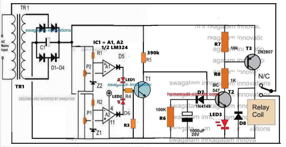
As suggested and confirmed by Mr. Ali who is a dedicated reader of this blog, the following home protector design can be used for implementing a much longer delay ON time surge protection.
Video Test Results
The following video shows the basic testing procedure of the above explained home protector circuit. The video was contributed by Mr. Ali.
A heartfelt thanks to Mr. Ali for his hard work. His testing and video contribution to homemade-circuits.com are much appreciated.
Conclusion
The above explained mains AC home protector circuit can be built and installed in homes for getting a full fledged protection from fluctuating high and low voltage situations and from sudden voltage in rush during power outages. If you have any further questions and doubts regarding the above concept, feel absolutely free to contact me through the below given comment box.


Questions & Answers
What voltages are the zener diodes,z1 and z2
They can be any value between 3v and 6v, 1/2watt.
Dear Sir Swagatam
Hello, I hope you are doing well and staying healthy. I am grateful for your kind response and for introducing the “Mains AC home protector circuit”. Would you please do me a favor and specify the number of pins on the IC LM324 ( A1 and A2 ) in the circuit diagram?
Thank you so much in advance
Sincerely
Ali
No Problem, Ali,
I would recommend using LM358 instead of LM324 since LM358 has two opamps, and we need only two opamps in the design.
Here’s the complete circuit diagram:
https://www.homemade-circuits.com/wp-content/uploads/2024/02/home-protector-circuit-using-IC-LM358.jpg
Dear Sir Swagatam
Hello. You have my heartfelt gratitude for the great favor you’ve done for me. I will surely do this project and will share you the result; my dear instructor.
He who never forgets your huge favor and kindness
Sincerely
Ali
You are most welcome Dear Ali,
I wish you all the best, and please share your results, and let me know if you have any further issues or doubts regarding the circuit.
Dear Sir Swagatam
Hello. Hope you are doing well
I would greatly appreciate it if you could kindly advise me on whether I am permitted to utilize a 220/9-0-9 transformer that I currently possess and adjust the 18V output of it to 12V using a 7812 regulator, in place of the 220/12-0-12 volt transformer. will the circuit work well then?
God bless you
Best regards
Ali
Thank you dear Ali,
Sorry, 7812 cannot be used since that would prevent the circuit from detecting the high low fluctuations.
However if you use a 9V relay then the 0-9V tap could be utilized for powering the circuit.
All the best to you, let me know if you have any further questions.
Thank you so much for your kind response, dear Sir Swagatam
I will definitely share the results
Best regards
Ali
You are most welcome Dear Ali,
Dear sir Swagatam
Hello. I am pleased to share that I have successfully assembled the circuit under title “Mains AC Home Protector Circuit” and it is functioning well. I want to express my gratitude for sharing such a wonderful circuit diagram.
After connecting the circuit, which was mounted on a breadboard, to the 15-volt rectified output of a 220/12v transformer, I had to adjust P2 slightly until the relay connected. Turning the P1caused the relay to switch off, indicating that the circuit is working perfectly.
The only challenge I encountered was that the commercial version I previously had, took a few minutes delay to power on the appliances when connected to the mains supply, a feature that I did not observe in your circuit design. I would be very glad if you please inform me how to solve this issue.
Thank you once again for providing this great circuit diagram, and for all your kindness too.
Best regards
Ali
That’s great Ali, thanks so much for verifying the results of this circuit.
Actually the parts R5 and C2 are specifically positioned to generate the intended delay on effect whenever the circuit is turned on.
When power is switched ON, C2 prevents the base of T2 to get the 0.6v biasing supply and keeps it turned off for sometime until C2 is fully charged via R5. However to compensate the presence of D8 we must add another diode in series with the emitter of T2, that should solve the issue and you should be able to get the initial switch on delay.
So please add a 1N4148 diode in series with T2 emitter, or maybe to further enhance the delay effect you can add a 3V zener diode in series with the T2 emitter, cathode of the zener will connect with the T2 emitter and the anode with the ground….let me know how it goes…all the best to you.
Dear Sir Swagatam
I hope you are doing well.
I am writing to share the results of the task you assigned to me. Here is what I have done based on your instructions:
1. I connected a 220V lamp to the relay and then plugged the circuit’s input into the mains supply. I adjusted P2 until the lamp turned on. Subsequently, I removed the wire that connects the emitter of Tr.2 to the ground and inserted a 3.0V Zener diode between the earth and the emitter of Tr.2. I waited for 20 minutes, but the lamp did not turn on. I then replaced the Zener diode with a 1N4148 diode and found that the result was the same as with the Zener diode. By adjusting P2 slightly, the lamp turned off, and rotating P1 caused the lamp to turn on.
2. Rotating P2 caused the lamp to turn off, and the output of pin 7 of LM358 was approximately 15V. Further adjustment of P2 resulted in the lamp turning on, with the output of this pin dropping to zero volts. Simultaneously, the output of pin 1 of LM358 IC also read zero volts. After adjusting P1, the lamp turned off, and the output voltage of pin 1 of LM358 was around 15 volts.
The circuit appears to be functioning correctly, but there is a particular issue that I am confident you, my esteemed instructor, Sir Swagatam, will be able to resolve.
Please excuse me for bothering you
I sincerely appreciate your kindness and assistance.
Thank you.
Warm regards,
Ali
Thank you Dear Ali,
I appreciate your efforts, however the setup procedure is a little elaborate and needs some thorough practical experimentation using a variable power supply.
Please refer to the above article, I have comprehensively explained how the presets P1, P2 needs to be set up and how the delay ON timing needs to be confirmed.
Please start reading from “Calculating the Tripping Points” and the full description that follows.
I have also updated the article with a new diagram with various LEDs for the appropriate indications.
Please let me know if you have any difficulty understanding the procedures.
Dear Sir Swagatam
Hello.
I would like to express my heartfelt gratitude for your detailed and thorough instructions on setting up the circuit. Your guidance was invaluable, as I had never encountered such procedures before. I appreciate the time you took to modify the circuit diagram and provide understandable detailed descriptions. Your willingness to assist visitors on your site is truly commendable.
Following your instructions, I successfully completed all nine steps using my 35V 3A bench power supply. However, I encountered a slight issue during the last step. ( This section of the article: As you lower the voltage, keep going until it reaches around 14V. At this point the LED1 should instantly turn ON, turning off LED3 and the relay (back to N/C point)) .LED1 was supposed to turn on when the voltage decreased to 14V from 19V, causing LED3 and the relay to turn off. Instead, this occurred at 16V. After that I adjusted P2 slightly, and LED1 turned on at 14V, and LED3 and the relay turned off after one second. Is there a reason for this?
I kindly request that you emphasize the following statement in bold and larger fonts: “This circuit performs incredibly well and is highly suitable for home appliances.”
I have a query my esteemed instructor: How can I extend the delay-ON time for the circuit to one minute or longer after connecting the circuit to the mains supply? By “delay ON time,” I am referring to the time it takes for a specific appliance to turn on after the circuit is powered on.
Once again, I am deeply thankful for your kindness and support.
Yours sincerely
Ali
Thank you so much Dear Ali for confirming the setting up procedures.
I think the LED1 turned ON at 16V because of a discrepancy in the P2 setting, because setting with an ordinary preset manually may not be accurate. I think you can try replacing the presets with multiturn presets, that would perhaps help you to get a much more accurate results from the presets.
You also said that LED3 and relay turned OFF after 1 second, this should not happen, because there’s nothing that would hold the LED3 and the relay for 1 second…If possible please investigate this issue from your end.
Regarding increasing the delay ON period of the relay, can you please specify why do you need this increased delay because a 1 or 2 second delay is actually enough to mitigate the switch ON surge hazard?
Prolonging the delay ON time would cause an unnecessary delay for the appliances to be turned ON, each time mains power is restored?
I will surely include the message in the article, as suggested by you, thank you for the suggestion.
Please let me know if you have any further doubts or queries.
Dear Sir Swagatam
Hello. Hope you are fine and healthy
I am writing in reference to my previous letter regarding the issue with LED1 turning on at 16V instead of the specified 14V. I am pleased to report that I have replaced both 10K pots. with multi turn ones. Upon setting and testing, I observed that while decreasing the voltage from 19V, LED1 illuminated precisely at 14V, in accordance with your instructions. Additionally, LED3 and the Relay turned off, aligning perfectly with your guidance: “As you lower the voltage, keep going until it reaches around 14V. At this point, the LED1 should instantly turn ON, turning off LED3 and the relay (back to N/C point).”
Regarding the significance of the delay-ON time, I would like to bring to your attention the frequent power interruptions experienced in my city. We face electricity cuts a few times every month, often resulting in severe fluctuations upon restoration. As a precautionary measure, most commercial mains protectors are sold here, delay the power supply to appliances for a few minutes after reconnection to mitigate the impact of these fluctuations.
Thank you very much for your favor and kindness
sincerely yours
Ali
Thank you so much Dear Ali,
I am glad you could adjust the presets correctly.
Now I understand the need for a long duration delay ON protection, it completely makes sense now.
I have tried to design the 1 minute delay-ON facility in the circuit, you can find the updated diagram in the following figure:
https://www.homemade-circuits.com/wp-content/uploads/2024/02/home-protector-circuit-with-long-delay-on.jpg
You can change the 1M resistor value and the 1000uF capacitor to tweak the delay ON period.
Also, I could not find a proper place to add the green LED, I think it can be added parallel to the relay coil with a series resistor.
Let me know if you have any further questions.
Dear Sir Swagatam
I hope you are doing well. Words are too weak to express the ultimate gratitude and thankfulness for your extreme favor in redesigning the circuit. Please accept my heartfelt thanks.
After purchasing a few 2N2907 transistor today, I assembled the circuit according to your new modifications. Unfortunately, it did not work; the relay did not connect even once. Replacing components related to the modified part of the circuit proved to be futile.
I reduced the 1 Mega ohm resistor to 100K and lower, but it didn’t work. There was no voltage across the 3V Zener diode either.
I reverted the circuit to its previous design, and it started working perfectly.
Please forgive me for bothering you and taking up your time. I am unsure if adding a simple timer circuit to the existing circuit, which is currently functioning well, is a good idea.
I will always remember your kindness.
Sincerely yours
Ali
Thank you Dear Ali, and sorry about the trouble you are facing.
I would like to tell you that the new circuit with longer delay time will surely work, you just have to do two things.
Replace the 3V zener diode with a 1N4148 (Cathode to ground) and tweak the 1M to some lower value.
However, I am glad the whole circuit is overall working for you.
Also I wanted to inform you that currently my site transitioning to a new host, so some comments might not be published during this period. Things will resolved within a couple of days.
Please keep up the good work. All the best to you.
Dear Sir Swagatam
Hello. Hope you are fine
I did both of your instructions diligently, carefully checked the wiring multiple times, and even substituted the circuit’s relay with an LED. However, the 2N2907 transistor did not conduct at all. I also experimented with it’s equivalents, including the BC327, 2N2905, and S9014, and as a last resort, removed the 1MR resistor. Regretfully, the result remained unchanged. I can only guess that the issue may lie in the potential defectiveness of the transistors though they were all new. It is my hope that assembling the components on a circuit board in the future may solve the problem.
“I am immensely grateful for your unwavering support, invaluable guidance, and the time you dedicated to responding and designing the complementary part of the circuit as per my need and request.”
Warmest regards
Ali
Thank you dear Ali, for your kind feedback,
However, i want to assure you that the delay ON timer using two transistors will work without any doubt, and I have tested it myself.
Please do some more modifications to make the circuit very obvious.
Please change 1M to 10k, replace the BC5547 emitter diode with an LED (anode to emitter, cathode to ground).
Let me know how it goes.
Dear Sir Swagatam, hello
Congratulations, Sir
Just two seconds after replacing the 1M resistor with a 10k resistor and connecting the Emitter of Tr2 to an LED (LED3) grounded, Tr3 conducted, and LED3 gleamed simultaneously with 7mA of current.”
The joy that flooded me at that moment was indescribable. It seems that the Emitter of Tr2 was the culprit causing the issue and bothering you a lot, since I had reduced the R5 to 10k earlier and it did not lead to Tr3 conduction. We can now consider LED3 as a Delay-on time indicator.
I extend my heartfelt gratitude for your unwavering support and patience in guiding me through this process.
The replacement of R5 with a 390k resistor successfully achieved a 115 seconds delay-on time, which perfectly suits my requirements. Maybe it is a good idea to publish the whole circuit diagram with it’s modifications in the main article.
please allow me to restate my request to highlight the following sentence ( or similar one in your own literature) prominently in bold and larger fonts for your website visitors: “This circuit performs exceptionally well and is highly recommended for home appliances.”
He who always remembers your kindness and generosity
Truly yours
Ali
Please note: At the time when I uploaded this response, The “Reply” field was off for all comments.
Thanks so much Ali, for updating the information. That’s great!
I am glad you could finally succeed with the delay ON timer circuit stage.
Yes, it was the 3V emitter zener diode and the 1M base resistor which were inhibiting the switch ON threshold of the transistor.
I will surely update the new complete diagram in the article soon, which was tested by you.
I have already put the message as suggested by you. You can find it at the top section of the above article.
I hope you are able to see the reply buttons for every comment now, please let me know if you don’t.
Dear Sir Swagatam
Hello, hope you are doing well
Yes, I can see the reply button now. Once again I thank you for all your assistance and updating the circuit diagram.
God bless you kind and lovely man
Best regards
Ali
Thank you Dear Ali, You are most welcome.
Please keep up the good work. All the best to you.
Dear Sir Swagatam
Hello, hope you are doing well
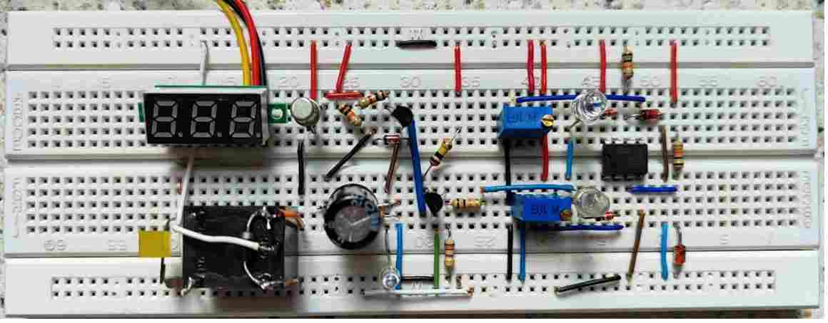
I have already sent two videos of the circuit’s performance mounted on a breadboard to your email address. I wanted to inform you that I have replaced R5=390K with a 100K resistor to record a short video so that You may consider publishing it on your site, if you wish.
As you may have noticed, when the mobile’s second-hand clock reaches 12 o’clock, I power on the circuit. Time passes slowly and the relay, subsequently the yellow LED connected to its NC pins, and the red LED placed between the T2 emitter and ground turn on after a 17-second delay (delay-On time).
Upon reducing the voltage to 14 volts, the red LED1 turns on, and upon increasing the voltage to 20 volts, the blue LED2 illuminates. That is all. I hope this video will be of interest to your visitors.
I hereby thank a lot Mr. Sambath for his appreciation
With warm regards,
ALi
Thank you so much Dear Ali,
The video is amazing and clearly shows the complete testing procedure for the last updated circuit.
Many thanks to you for your kind contribution!! All the best to you, and please keep up the good work.
…I have updated the video clip in the above article.
Dear Sir Swagatam
Thank you so very much for publishing the video. I am so pleased you like it. in fact, You have embarrassed me with your high praise and thanking for something that I do not consider remarkable. I am very grateful for the kind and generous person that you are, and for helping others with all your heart.
Thank you very much my patient instructor.
Best regards
Ali
No problem Dear Ali, you are most welcome, I appreciate your kind words.
Hello Sir,
Your ckt is really good.I also thank Mr Ali for the pain and effort he took to modifie the delay circuit. suggestion fr my side is
1.Led3 to be connected in the same polarity between T2 collector and R8. led 3 better a green one. in course of time improper function of T2 can happen it is good for the BE voltage of T2.
2.Better to provide a100 mfd 25v cap parallel to R7 negative of cap going to the base of T3 to avoid chattering of relay due to power supply variations now it will not be there but it can happen any time.
3.what is the regulated +vcc voltage of the icis it 5v. Are you using a regulator or voltage divider resistor with zener. If we use a12-0-12v transformer we can avoid 2 rect diodes in the pcb to save space and time . A rly 100 ohms / 12v takes 120ma+ other ckts 30 max ie 150ma ,relay is on most of the time so I feel 12v 750 ma is ideal and easily avalible is 12v 1 amp.
Sir these are my suggestions you can correct me if I am wrong.
Regards V.Sambath Kumar.
Thank you Sambath,
I appreciate your suggestions.
The LED3 in the last diagram must be connected with the same polarity as shown. Yes, a green LED would be better for LED3.
You can add a 100uF across base/emitter of T3 for a reliable operation of the relay.
A bridge rectifier is always the best option which allows the transformer to be more compact compared to a 12-0-12V, because in a 12-0-12 trafo an extra 12V winding is used which can make the transformer unnecessarily bulkier.
The maximum operating voltage of an LM358 is 32V which is quite sufficient for the above project.
I think a 12V 200 ohm relay can be used which will have contacts rated at 20 amps, enough for any household electrical application, so a 500 ma transformer should do the job.
Sir,
Thank you very much for your valuable tips and advice.
Regards V.Sambath kumar
You are welcome Sambath.
dear sir….thanks for giving us a very important project. yoi always provide a helpfull circits, and your passion to guide awesome.
sir as usual i need your support. as you know i am not much famlier with ics diagrams sir plz provide me diagram like you help me in timmer circut cd4060 and cd4017 with ic/transisters pinout. plz
No problem Ghulam, I will surely try to help.
Please tell me which diagram you are not able to understand, I will try to figure it out for you.
sir that ic lm358 section a1 and a2, pots connectivity…this section diagram i m not understaing. plz make it with ic and pot pins plz
Ghulam, It is actually very easy to replace the LM324 opamps with LM358 opamps. Please see LM358 diagram below, just replace the two opamps pinouts in the diagram with the pinout of the LM358, Next connect pin4 to ground and pin8 to positive:
https://www.homemade-circuits.com/wp-content/uploads/2019/06/LM358-internal-layout.png
Let me know if you have any difficulties.
thank you very much sir, now i can try to make easly. a lot of thanks. appriciated your support.
You are welcome Ghulam.
sir actully i am umable to understand symbol of ic, i am requesting that plz provide me full project diagram as like timer project, with cd4060, and also you guide me before changeover circut with cd4017 and cd4060. with actuall shape of ic lm358, with pins conectivity. hope you got my point. i m sorry to disturb you.
Hi Ghulam,
You can check the updated image in the following link, using LM358:
https://www.homemade-circuits.com/wp-content/uploads/2024/03/home-protector-circuit-using-LM358.jpg
hi sir,
hope all is going well. sir i have two questions, can we replace transister 2n2907 with bc557? or any other pnp? sir can we add current protection? like we are using 30amp relay, if load more than 30 amp load cutoff. or we can set 10 or 15 amp like that. plz add this featuer also plz. i am going to make this project, but waiting for update version plz. plz provide me diagram
thanks
Hi Ghulam,
For a 30 amp relay, the coil resistance could be 100 ohms or lower, which a Bc557 might not be able to handle. Therefore, you must use a 2n2907, or 8550 or maybe BD140 transistor as the relay driver.
I will surely help you to add an over-current protection to the circuit, but first please try the basic setup explained in the above article.
If you succeed with it then i will show you to integrate an over-current stage with the circuit.
If you go step-wise it will be easier for you to troubleshoot, in case something goes wrong.
ok sir, i will update you soon. a lot of thanks
Sure, all the best to you.
Hi
I make the Mr. Ali circuit with extended delay but
Delay happening only on startup not if we cut switch on off Or intermediate I tried r5 100 k and 200k with both resistor delay time was 15sec and 28sec respectively but no delay time if we just switch off and on in 1 sec but after 5 sec I get delay around 5 sec and after wait around 20 sec. I got 15 sec delay pls guide
Thanks for trying the circuit, I will try to solve the problem.
You are right, it is because the 1000uF capacitor is not discharging quickly via R6, and we cannot make R6 too small, otherwise T2 won’t conduct.
You can replace the the R6 with a PNP transistor as shown in the following diagram and see if it helps to quickly discharge the 1000uF capacitor or not. For the zener diode you can take a 3V zener.
https://www.homemade-circuits.com/wp-content/uploads/2024/05/timer-capacitor-discharge.jpg
Hi
How to discharge c2 instantly delay not happening cause c2 remains charged and discharge very slowly after full discharge delay happened as usual