• Skip to main content
  • Skip to primary sidebar

Homemade Circuit Projects

Need circuit help? Post them in the comments! I've answered over 50,000!

Blog | Categories | About | Contact | Calculators-online
You are here: Home / Meters and Testers / LM317 IC Tester Circuit – Sort Out Good ICs from Faulty Ones


LM317 IC Tester Circuit – Sort Out Good ICs from Faulty Ones

Last Updated on January 14, 2021 by Swagatam 7 Comments

Here is simple but handy testing circuit for LM317 adjustable voltage regulator IC. I am sure it can be used to test other similar ICs like LM117, LM158, LM358 etc.

Table of Contents
  • How it Works

The circuit is pretty straightforward. The circuit is based on normal configuration of adjustable voltage regulator.

How it Works

For details follow https://www.homemade-circuits.com/2011/12/how-to-build-simplest-variable-power.html

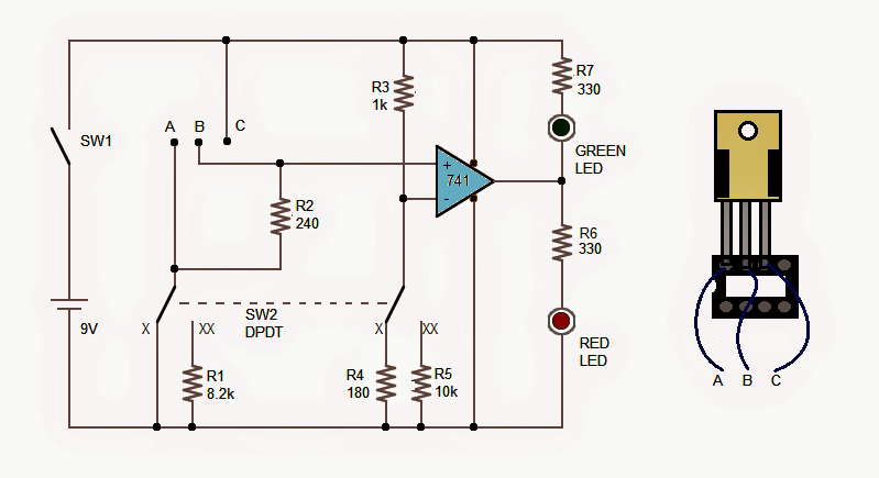
A DPDT switch is used to connect the ADJ pin of the IC to either ground or to the resistor R1. When connected to ground, the output should be at the lowest level around 1.2V and when connected to R1 the output should be the maximum level (around 7.5V for 9V input). Next, LM741 is used to compare the output with a preset voltage level.

When the DPDT switch is in X position the ADJ pin is connected to ground and the (-)ve input of 741 is connected to R4.

The potential divider R3+R4 gives about 1.37V at (-)ve input of 741 which is compared with the output from the Voltage Regulator IC.

In this case it should be about 1.2V which less than 1.37V hence the output of 741 remains low and the green LED glows. If for some reason the output from the voltage regulator IC is more than 1.37V the output of 741 goes high and the red LED lights up, indicating malfunction of the v/reg IC.

When the DPDT switch is in XX position the ADJ pin is connected to R1 and the (-)ve input of 741 is connected to R5. The potential divider R3+R5 gives about 8.1V at (-)ve input of 741 which is compared with the output from the Voltage Regulator IC.

In this case it is should be about 7.5V which less than 8.1V hence the output of 741 remains low and the green LED glows. If for some reason the output from the voltage regulator IC is more than 8.1V the output of 741 goes high and the red LED lights up, indicating malfunction of the v/reg IC.

If none of the LEDs glows, it indicates that input pin and ADJ pin of the voltage regulator IC is short because the +9V are connected to ground via ADJ pin.

An 8-pin IC base or simply a 3-pin female connector may be used to hold the v/reg. IC for testing.

Designed, Written and Submitted by: Abu-Hafss

warning message: electricity is dangerous, proceed with caution
LM317Tester

You'll also like:

  • 1.  Simple Arduino Digital Ohmmeter Circuit
  • 2.  10 Useful Function Generator Circuit Diagrams Explained
  • 3.  Make a Workbench Multimeter With the IC 741
  • 4.  LED Brightness and Efficiency Tester Circuit
  • 5.  Circuit Tester Probe – PCB Fault-Finder
  • 6.  How to Check a MOSFET Using a Digital Multimeter

Filed Under: Meters and Testers Tagged With: Faulty, Good, LM317, Ones, Sort, Tester

About Swagatam

I am an electronics engineer and doing practical hands-on work from more than 15 years now. Building real circuits, testing them and also making PCB layouts by myself. I really love doing all these things like inventing something new, designing electronics and also helping other people like hobby guys who want to make their own cool circuits at home.

And that is the main reason why I started this website homemade-circuits.com, to share different types of circuit ideas..

If you are having any kind of doubt or question related to circuits then just write down your question in the comment box below, I am like always checking, so I guarantee I will reply you for sure!

Previous Post: « Digital Clock Activated Water Level Controller Circuit
Next Post: DIY Taser Gun Circuit – Stun Gun Circuit »

Reader Interactions

Comments

  1. Doru M. says

    March 28, 2023 at 1:32 pm

    Hi sir, I guess there is a mistyping in the value of R1, instead of 8.2k, the value has to be 1.2k.
    According with formula from LM317 datasheet:

    Vout = 1.25V x (1 + R1/R2) (your diagram resistors indexes)

    For 7.5V and R2 = 240, a ratio 5:1 for R1 regarding of R2 value is ok. So I think the right value for R1 is 1.2k.

    Thanks for diagram idea and best regards!

    Reply
    • Swagatam says

      March 28, 2023 at 5:32 pm

      Thank you Doru,
      You are absolutely correct, the value of R1 should be 1.2K for the IC to generate 7.5V

      Reply
  2. Jorge says

    April 16, 2022 at 11:33 am

    Hi, my friend, Swagatam!!!
    Let me speak on this issue.
    I think that the main disadvantage of this circuit is that you will not be able to check the IC for the peak current, and this is the most important thing. We all know that according to the datasheet, the LM317 passes up to 1.5 amperes, but modern Chinese fakes give out no more than 300 milliamps.
    Agree that this is the main indicator of the quality of the IC LM317.
    I have already encountered this problem, when out of 10 IC’s only 2 were working normally.
    Unfortunately, this circuit becomes practically useless for testing LM317, if only for an internal break.
    It is possible that this will give you an idea of ​​how to make a full-fledged tester for these IC’s.
    This is my personal opinion, which may not coincide with the public.

    Reply
    • Swagatam says

      April 16, 2022 at 8:13 pm

      Thank you Jorge, for your valuable feedback.

      You may be correct, however an easy way to confirm the current is by attaching a 2 amp 12V lamp at the output. If the lamp illuminates brightly will confirm the 1.5 amp output from the IC.

      Reply
  3. Pierre Au says

    January 13, 2021 at 10:36 pm

    Hello,
    Very clear and simple to understand tuto.
    Many thanks.
    Where to buy the PCB for this LM317 tester?
    Best regards.
    Pierre Au,

    Reply
    • Swagatam says

      January 14, 2021 at 8:28 am

      Thank you, sorry we don’t sell PCBs, you will have get it from a designer.

      Reply
      • Pierre Au says

        January 14, 2021 at 9:03 am

        Thousand thanks for your kind answer.
        Best regards.
        Pierre

        Reply

Need Help? Please Leave a Comment! We value your input—Kindly keep it relevant to the above topic! Cancel reply

Your email address will not be published. Required fields are marked *

Primary Sidebar

circuit simulator image

Subscribe to New Posts


Categories

  • Arduino Projects (89)
  • Audio and Amplifier Projects (132)
  • Automation Projects (17)
  • Automobile Electronics (101)
  • Battery Charger Circuits (83)
  • Datasheets and Components (104)
  • Electronics Theory (143)
  • Free Energy (37)
  • Games and Sports Projects (11)
  • Grid and 3-Phase (19)
  • Health related Projects (25)
  • Home Electrical Circuits (12)
  • Indicator Circuits (14)
  • Inverter Circuits (88)
  • Lamps and Lights (142)
  • Meters and Testers (69)
  • Mini Projects (46)
  • Motor Controller (64)
  • Oscillator Circuits (27)
  • Pets and Pests (15)
  • Power Supply Circuits (108)
  • Remote Control Circuits (50)
  • Security and Alarm (64)
  • Sensors and Detectors (101)
  • Solar Controller Circuits (59)
  • Temperature Controllers (42)
  • Timer and Delay Relay (49)
  • Transmitter Circuits (29)
  • Voltage Control and Protection (39)
  • Water Controller (36)


Other Links

  • Privacy Policy
  • Cookie Policy
  • Disclaimer
  • Copyright
  • Videos
  • Sitemap


People also Search

555 Circuits | 741 Circuits | LM324 Circuits | LM338 Circuits | 4017 Circuits | Ultrasonic Projects | SMPS Projects | Christmas Projects | MOSFETs | Radio Circuits | Laser Circuits | PIR Projects |

Social Profiles

  • Twitter
  • YouTube
  • Instagram
  • Pinterest
  • My Facebook-Page
  • Quora
  • Stack Exchange
  • Linkedin


  • Recent Comments

    • Swagatam on How Shunt Regulator TL431 Works, Datasheet, Application
    • SA on How Shunt Regulator TL431 Works, Datasheet, Application
    • Farmtech on Free Energy Generator Circuit – The N-Machine
    • Nitesh Agrawal on How to Design Simple LED Driver Circuits
    • Swagatam on How to Design Simple LED Driver Circuits

    © 2025 · Swagatam Innovations