The full form of LED is Light Emitting Diode. LEDs are special type of semiconductor diodes which emit light in response to a potential difference applied across their terminals, hence the name light emitting diode. Just like a normal diode LEDs also have two terminals with polarity, namely anode and cathode. To illuminate an LED a potential difference or a voltage is applied across its anode and cathode terminals.
Today, LEDs are extensively used for manufacturing high bright state-of-the-art LED lamps. These are also popularly used for manufacturing decorative LED string lights, and LED indicators.
Brief History
Despite the fact that LEDs are considered a product of the high-tech semiconductor industry today, their illuminating property was initially identified many many years ago. The first person to notice the LED light effect was one of Marconi's engineers, H. J. Round, who is also well-known for several vacuum tube and radio inventions. He happen to discover this in the year 1907 while researching with Marconi on point-contact crystal detectors.
In 1907, Electrical World magazine was the first to report on these breakthroughs. The LED concept remained dormant for several years until being rediscovered in 1922 by Russian scientist O.V. Losov.
Losov resided in Leningrad, where he was tragically killed in World War 2. It is possible that most of his designs were lost in the war. Although he filed a total of four patents between the years of 1927 and 1942, his research was not recognized until after his death.
The LED concept reappeared in 1951, when a group of scientists under K. Lehovec began investigating the effect. The investigation proceeded with the participation of other organizations and researchers, including W. Shockley (inventor of the transistor). Eventually, the LED concept underwent significant refinement and began to be commercialized in the late 1960s.
Which Semiconductor Material is used in a LED Junction?
In essence, light-emitting diodes are a specialized PN junction made using a compound semiconductor.
Silicon and germanium are the two most widely used semiconductors, however since these are only elements, LEDs cannot be made from them.
Conversely, materials like gallium arsenide, gallium phosphide, and indium phosphide that combine two or more elements are frequently utilized to make LEDs. Gallium arsenide, for instance, has a valency of three and arsenic has a valency of five, and therefore, both are classified as group III -V semiconductors.
Materials belonging to group III-V can also be used to create other compound semiconductors.
When a semiconductor junction is forward biased, holes from the P-type region and electrons from the N-type region enter the junction and combine, just as they would in a normal diode.
Current moves through the junction in this manner.
Energy is released as a result, some of which are emitted like photons (light). In order to guarantee that the least amount of photons (light) is absorbed by the structure, the P-side of the junction, which produces the majority of the light in most cases, is positioned closest to the device's surface.
The junction is required to be perfectly optimized and the right materials need to be used to create visible light. The infrared region of the spectrum is where pure gallium arsenide emits its energy.
How LEDs get their Colors
Aluminum is introduced to the semiconductor to produce aluminium gallium arsenide, which shifts the LED light into the bright red end of the spectrum (AIGaAs).
Red light can also be produced by adding phosphorus.
Various materials are utilized for other LED colors. For instance, gallium phosphide emits green light, while yellow and orange light is produced by aluminium indium gallium phosphide. The majority of LEDs are made of gallium semiconductors.
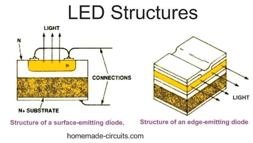
LEDs are Manufactured with Two Structures
The surface-emitting diode and the edge-emitting diode, which are seen in Figs. 1 A and B, respectively, are the two primary architectures utilized for LEDs. The surface-emitting diode is the most popular of them since it produces light over a broader angle.
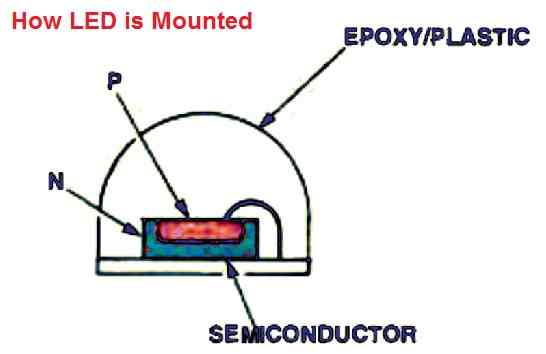
After manufacturing, the LED structure needs to be enclosed in such a way that it can be safely used without any damage to the LED.
The majority of the tiny LED indicators are encapsulated in an epoxy glue with a refractive index that lies somewhere between that of the semiconductor and that of the surrounding air (see Fig. 2 below). The diode is thus perfectly safeguarded, and the light is transferred to the outer world in the most effective manner.
LED Forward Voltage (VF) Specification
Since LEDs are current sensitive devices, the applied voltage must never exceed the minimum forward voltage spec of the LED. The forward voltage specification of an LED (VF) is simply the optimal voltage level which can be used to illuminate the LED safely and brightly. If the current exceeds the forward voltage spec of the LED, the LED will burn and get permanently damaged.
In case, the supply voltage is higher than the forward voltage of the LED, a calculated resistor is used in series with the supply to limit the current to the LED. This ensures that the LED is able to safely illuminate with optimal brightness.
The forward voltage value of most LEDs today is around 3.3 V. Whether it is a red, a green or a yellow LED, all typically can be illuminated by applying 3.3 V across their anode and cathode terminals.
The supply voltage to the LED must be a DC. An AC can be also used but then the LED should have rectifier diode connected with it. This ensures that the change of polarity of the AC voltage does not cause any harm to the LED.
Limiting Current
LEDs, just like normal diodes, have no inherent current limiting. As a result, if it is connected directly across a battery, it will get burned.
If the supply DC is around 3.3 V then the LED will not require a limiting resistor. However if the supply voltage is higher than 3.3 V, then a resistor will be required in series with LED terminal.
The resistor can be connected either in series with the anode terminal of the LED, or with the cathode terminal of the LED.
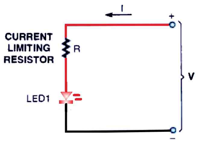
To avoid damage, a resistor must be connected to the circuit to control the current. Normal indicator LEDs have a maximum current specification of roughly 20 mA; if the current is limited below this, the light output of the LED will reduce proportionately.
As illustrated in Fig. 3 above, the voltage across the LED itself may need to be considered while estimating the amount of current consumed. Because if the voltage increases the current consumption will also increase proportionately.
The formula for calculating the limiting resistor is as given below:
R = V - LED FWD V / LED Current
- Here V represents the input DC supply.
- LED FWD V is the forward voltage specification of the LED.
- LED current denotes the maximum current handling capacity of the LED.
Let's assume V = 12 V, LED FWD V = 3.3 V, and LED current = 20 mA, then the value of R can be solved in the following manner:
R = 12 - 3.3 / 0.02 = 435 Ohms, the nearest standard value is 470 Ohms.
Wattage will be = 12 - 3.3 x 0.02 = 0.174 watts or simply a 1/4 watt will do.


Need Help? Please Leave a Comment! We value your input—Kindly keep it relevant to the above topic!