• Skip to main content
  • Skip to primary sidebar

Homemade Circuit Projects

Need circuit help? Post them in the comments! I've answered over 50,000!

Blog | Categories | About | Contact | Calculators-online
You are here: Home / Water Controller / Light Activated Water Level Controller Circuit

Light Activated Water Level Controller Circuit

Last Updated on May 27, 2019 by Swagatam 2 Comments

The light activated water level controller circuit explained here has the advantage of being corrosion free and much reliable than the traditional moisture sensor type of water sensors.

Table of Contents
  • Circuit Operation
  • Circuit Diagram

Circuit Operation

One slight downside of this LDR based sensor is that the tank interior always needs to be illuminated by some kind of light source such as a bulb or a LED.

A  LDR sensor is configured with a IC 741 opamp and adjusted carefully such that the light falling over the LDR keeps the pin3 of the IC low in response to a focused light source and with reference with pin2 set voltage.

In an event the light across the LDR is disturbed, induces an imbalance across the pinouts of the IC triggering the opamp output to go high and activate the connected relay and the load.

In the present light activated water level controller circuit, an LDR is utilized and positioned across the the area of the tank where the level is to be monitored, or a relay is to be activated in response to a rise in the water level.

Circuit Diagram

waterlevelsensor 1

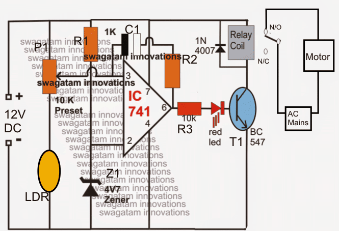
As long as there's an absence of water across the sensing zone, the LDRs experience the incident light (positioned from the opposite side, inside the tank) which in turn keeps pin3 of the IC low, however when water starts rising and tends to cover the LDR in the path, reverts to a high at pin3 of the IC which instantly prompts the opamp output to go high activating the relay and the pump.

A hysteresis control feedback resistor across the opamps (R2/C1)) make sure that the once the situation is sensed it stays latched for some predetermined time and the pump motor is allowed to run until the water has reached the bottom of the tank.

The time for which the opamp stays latched may be determined by adjusting the feedback resistor connected between the output and the input pins of the opamp.

You'll also like:

  • 1.  Cheap Semi Automatic, Tank Water Over Flow Controller Circuit
  • 2.  Car Tank Water Sensor Circuit
  • 3.  Simple Water Level Indicator Circuits (with Images)
  • 4.  Analogue Water Flow Sensor/Meter Circuit – Check Water Flow Rate
  • 5.  Programmable Humidity Controller Circuit
  • 6.  Digital Clock Activated Water Level Controller Circuit

About Swagatam

I am an electronics engineer with over 15 years of hands-on experience. I am passionate about inventing, designing electronic circuits and PCBs, and helping hobbyists bring their projects to life. That is why I founded homemade-circuits.com, a website where I share innovative circuit ideas and tutorials. Have a circuit related question? Leave a comment.... I guarantee a reply!

Previous Post: « Infrared Remote Control Safe Lock Circuit
Next Post: Simple Cellphone Jammer Circuit »

Reader Interactions

Comments

  1. Chandan Parashar says

    September 16, 2015 at 4:42 am

    dear swagatam,
    what should be rating of R2 and C1 to have a latch up time of say 2 hours.
    thanks in Advance.

    Reply
    • Swagatam says

      September 16, 2015 at 11:27 am

      Dear chandan, it'll have to be determined with some trial and error, it would be difficult to predict fixed values without a practical test.

      Reply

Need Help? Please Leave a Comment! We value your input—Kindly keep it relevant to the above topic! Cancel reply

Your email address will not be published. Required fields are marked *

Primary Sidebar

Subscribe to New Circuit Ideas

Categories

  • Arduino Projects (87)
  • Audio and Amplifier Projects (132)
  • Automation Projects (17)
  • Automobile Electronics (101)
  • Battery Charger Circuits (83)
  • Datasheets and Components (104)
  • Electronics Theory (143)
  • Free Energy (37)
  • Games and Sports Projects (11)
  • Grid and 3-Phase (19)
  • Health related Projects (25)
  • Home Electrical Circuits (12)
  • Indicator Circuits (14)
  • Inverter Circuits (87)
  • Lamps and Lights (142)
  • Meters and Testers (69)
  • Mini Projects (46)
  • Motor Controller (64)
  • Oscillator Circuits (27)
  • Pets and Pests (15)
  • Power Supply Circuits (108)
  • Remote Control Circuits (50)
  • Security and Alarm (64)
  • Sensors and Detectors (101)
  • Solar Controller Circuits (59)
  • Temperature Controllers (42)
  • Timer and Delay Relay (49)
  • Transmitter Circuits (29)
  • Voltage Control and Protection (37)
  • Water Controller (36)

Calculators

  • Battery Back up Time Calculator
  • Capacitance Reactance Calculator
  • IC 555 Astable Calculator
  • IC 555 Monostable Calculator
  • Inductance Calculator
  • LC Resonance Calculator
  • LM317, LM338, LM396 Calculator
  • Ohm’s Law Calculator
  • Phase Angle Phase Shift Calculator
  • Power Factor (PF) Calculator
  • Reactance Calculator
  • Transistor Astable Calculator
  • Transistor base Resistor Calculator
  • Voltage Divider Calculator
  • Wire Current Calculator
  • Zener Diode Calculator
  • Filter Capacitor Calculator
  • Buck Converter Calculator
  • Boost Converter Calculator
  • Solar Panel, Inverter, Battery Calculator
  • Wire Current Calculator
  • SMPS Transformer Calculator
  • IC SG3525, SG3524 Calculator
  • Inverter LC Filter Calculator

People Also Search

555 Circuits | 741 Circuits | LM324 Circuits | LM338 Circuits | 4017 Circuits | Ultrasonic Projects | SMPS Projects | Christmas Projects | MOSFETs | Radio Circuits | Laser Circuits | PIR Projects |

Recent Comments

  • Swagatam on Real MPPT Solar Charger Circuit Using Arduino, LCD, and Manual/Auto Switch
  • Swagatam on AC Motor Speed Controller Circuits using Back EMF
  • Swagatam on DC to DC Converter Circuits using SG3524 [Buck, Boost Designs]
  • Swagatam on Understanding SG3525 IC Pinouts
  • Swagatam on 7 Simple Inverter Circuits you can Build at Home

Company

  • Privacy Policy
  • Cookie Policy
  • About Me
  • Contact
  • Disclaimer
  • Copyright
  • Videos
  • Sitemap

Social Profiles

  • Twitter
  • YouTube
  • Instagram
  • Pinterest
  • My Facebook-Page
  • Quora
  • Stack Exchange
  • Linkedin
  • © 2025 · Swagatam Innovations