These smart, intelligent battery charger will charge a Li-IOn battery rapidly by monitoring 3 crucial parameters, which are constant current, constant voltage and constant 25 degrees Celsius temperature.
The post elaborately explains 3 Hi-End, automatic, advanced, single chip CC/CV or constant current, constant voltage 3.7V Li-Ion battery charger circuits, using specialized Hi-End IC TP4056, IC LP2951, IC LM3622, with battery temperature sensing and termination facility.
Design#1
CIRCUIT DESCRIPTION
The first design is probably the smartest one, incorporating the IC TP4056 which is a comprehensive constant-current (CC), constant-voltage (CV) linear battery charger IC specially designed for safely charging single cell lithium-ion batteries.
It comes with a SOP package and hardly any external component count making the IC TP4056 specially applicable for portable Li-Ion charging applications.
In addition, the TP4056 can also work with USB and wall socket based adapter supplies.
This smart design does not depend on any blocking diode due to the presence of an internal PMOSFET architecture which is configured to prevent any sort of negative Charge Current in the Circuit.
A special Thermal feedback loop is included in order to regulate the charge current to limit the body temperature while using in high power operation mode or with high ambient temperatures.
The full charge voltage is fixed at 4.2V, while the charge current can be adjusted externally through a given single resistor.
The IC TP4056 is featured to automatically shut down the charging cycle as soon as the charge current has dropped to 1/10th the set value, after the final float voltage is accomplished.
Some of the other mains features of this IC TP4056 include a built-in current monitor circuitry, an under voltage lockout, an automatic recharge resumption, and a couple of status pinouts to indicate full-charge cut off and the supply input voltage switch ON.
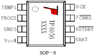
IC TP4056 image and pinout arrangement
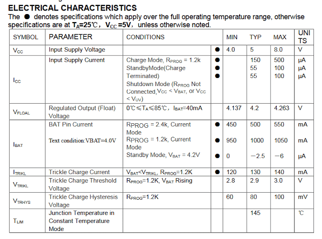
FEATURES and SPECIFICATIONS
- Charge Current may be programmed to a max 1000mA
- The circuit can be free of power devices, Sensing Resistor or a Blocking Diode.
- A full fledged Linear Charger in SOP-8 Package for charging applications of Single Cell Lithium-Ion Batteries.
- Designed to Produces a Constant-Current/Constant-Voltage Output
- Capable of Charging Single Cell Li-Ion Batteries through Direct USB Port plugin
- Internally set 4.2V constant Charge Voltage with +/-1.5% Accuracy
- Includes an Automatic Recharge initialization.
- A double LED compatible Charge Status Output Pins for indication purpose
- C/10 Charge Termination or auto shut down feature
- Trickle charge is initiated as soon as a 2.9V threshold is reached.
·An Internal Soft-Start processor Limits and inhibits Inrush surge Current - Comes with a 8-Lead SOP Package, The Radiator needs to be connected to GND.
ABSOLUTE MAXIMUM RATINGS
- Input Supply Voltage(VCC):-0.3V~8V ·
- TEMP:-0.3V~10V
- CE:-0.3V~10V
- BAT Short-Circuit Duration:Continuous
- BAT Pin Current:1200mA
- PROG Pin Current:1200uA
- Maximum Junction Temperature:145°C
- Operating Ambient Temperature Range:-40°C~85°C
- Lead Temp.(Soldering, 10sec):260°C
APPLICATIONS
- Cellphones, PDAs, GPS
- Charging Docks and Cradles
- Digital Still Cameras, Portable Devices
- USB Bus-Powered Chargers,Chargers
Pinout specification and functioning details of TP4056 IC
TEMP (Pin 1) :Temperature Sense Input
Hooking up TEMP pin with an NTC thermistor's output in Lithium ion battery pack. If TEMP pin’s voltage falls below 45% or beyond 80% of supply voltage VIN for a minimum 0.15 seconds or more, this indicates that battery’s temperature is simply too high or overly reduced respectively, and charging at this position is stopped. The temperature detection feature could be disabled by joining the TEMP pinto the ground rail.
PROG (Pin 2): is associated with the Constant Charge Current Setting and may be set by attaching a resistor RI(prog) from this pin2 to GND.
While in the precharge mode, the ISET pin’s voltage is regulated to around 0.2V. and in constant charge current mode, the ISET pin’s voltage is regulated to around 2V. Within all modes and in the process of charging, the voltage on ISET pin could be utilized to monitor the charge current through a meter.
GND (Pin3): Ground Terminal
Vcc (Pin 4): Positive Input Supply Voltage
VIN is the power supply input for the internal circuit to operate. Any time VIN falls at around 30mv below the BAT pin voltage, TP4056 goes into low power sleep mode, reducing BAT pin’s current below 2uA.
BAT (Pin5): Battery Connection Pin.
Link the positive terminal of the battery to BAT pin. BAT pin consumes lower than 2uA current whenever the chip is in the disable mode or in sleep mode. BAT pin offers charge current for the connected battery and presents it with a voltage regulation of precise 4.2V.
(Pin6): Open Drain Charge Status Output, Whenever the battery reaches the Charge Termination shut off point, this pinout is dragged low through an in-built switch, but normally this pin remains in high impedance status.
(Pin7): Open Drain Charge Status Output Once the battery is connected and begins charging, this pinout is taken low by an in-built switch, in any other case the pin is held at high impedance condition.
CE (Pin8): Chip Enable Input. A high input here enables the unit to be in the typical operating mode.
Towing the CE pin to a logic low level will force the TP4056 chip into a disable or shut down mode.
The CE pin is compatible and could be associated wit TTL or CMOS logic triggers.
Important Calculations
Charge Current Setting (Rprog Calculation):
The TP4056 uses a resistor (Rprog) connected between the PROG pin and ground to set the charge current.
Formula:
Icharge = 1000 / Rprog
Where:
Icharge = Desired battery charge current in milliamps (mA)
Rprog = Resistor value in ohms (Ω)
Example Calculation:
If Icharge = 1A (1000 mA):
Rprog = 1000 / 1000 = 1 kΩ
If Icharge = 500 mA:
Rprog = 1000 / 500 = 2 kΩ
Charging Voltage:
The charging voltage is pre-set at 4.2V which is suitable for all standard 3.7V Li-Ion cells. No configuration is required for this parameter.
Input Voltage Range:
The TP4056 supports an input voltage range of 4.5V to 8V. Please ensure that the power source supplies a stable voltage within this range.
Thermal Regulation:
The IC has an internal thermal regulation feature, in which the charging current automatically reduces if the junction temperature exceeds 120°C. Please make sure to include adequate heat dissipation to get optimal performance.
Battery Full Detection:
The IC stops charging when the battery voltage reaches 4.2V and the charge current drops below 1/10th of the set charge current.
Formula for End-of-Charge Current:
Iend = Icharge / 10
For example:
If Icharge = 1000 mA, then Iend = 100 mA.
If Icharge = 500 mA, then Iend = 50 mA.
Input Capacitor (CIN):
A capacitor is recommended at the input to stabilize the input voltage.
Typical Value:
CIN = 1 μF to 10 μF
Output Capacitor (COUT):
A capacitor is recommended at the output to ensure stable operation.
Typical Value:
COUT = 1 μF to 10 μF
Protection Diode (Optional):
You can use a Schottky diode (DIN) to be placed at the input to protect the IC from reverse polarity or surges.
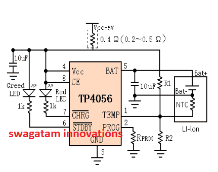
Li-Ion Battery charger circuit using TP4056
The following design represents the typical Li-ion battery charger circuit with constant current and constant voltage features and with auto termination at 4.2V.
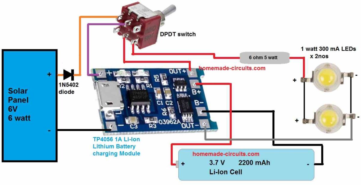
TP4056 Solar Lamp Circuit
The following image shows a highly efficient 2 watt solar LED lamp circuit using the IC TP4056 charger.
This circuit could be used as a vendor solar lamp unit.
The following figure shows the LED status indication details for the above discussed CV, CC Li-Ion battery charger circuit.
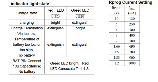
Courtesy: NanJing Top Power ASIC Corp.
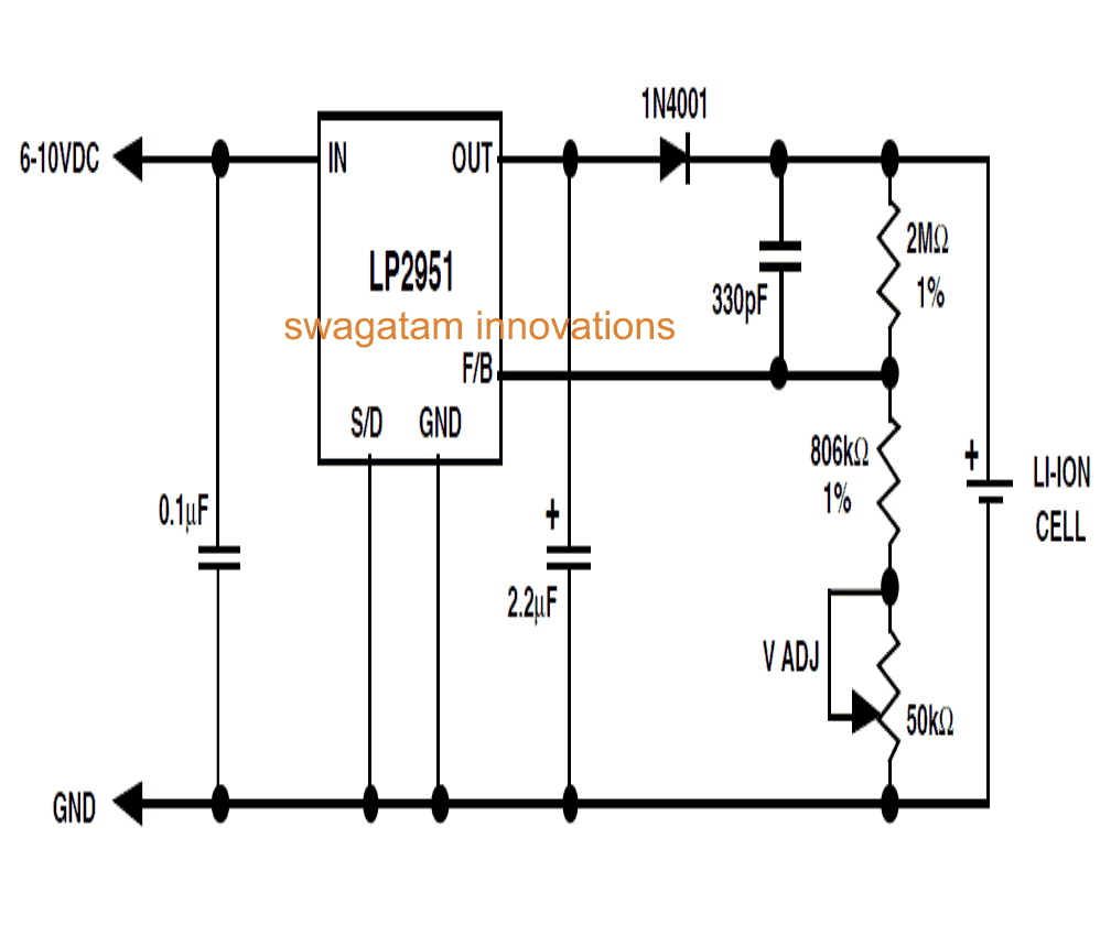
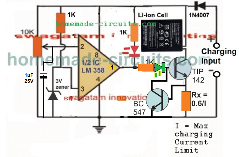
Design#2: Intelligent Li-Ion battery charger using just a single IC LP2951
In this post I have explained a very simple yet safe Li-Ion battery charger circuit using just a single IC LP2951.
Unlike lead acid batteries one good thing about the Li-Ion batteries is that they can be charged at 1C rate initially. It means the charging current may be as high as the rated AH of the battery at the onset.
The design I have I have explained in this article can be used for charging a single 3.7V Li-ion cell or a standard cell phone battery externally at a relatively slower rate.
The diagram depicts a configuration which was used for charging a Li-Ion cell of a portable stereo unit.
The charging specification of the circuit may be summarized as under:
- Maximum charging current = 150mA
- Full charge volt = 4.2V +/- 0.025V
- Charge Current = set at current limit charge mode.
How it Works
In the given circuit the IC LP2951 becomes the main active component which has been specifically chosen because it is capable of delivering an output voltage that's very stable over temperature.
The device also features an in-built current regulation system which limits the output from producing current above the 160mA mark.
Furthermore the IC is entirely short circuit proof and incorporates a thermal shut down facility.
The shown resistor values are precisely selected such that the IC generates an exact 4.2V at its output where the cell is connected.
The trimmer is added for refining the voltage in case there's any discrepancy with the resistor tolerance and ratings.
Initially when the particular discharged cell has a voltage level that's below the 4.2V, the IC generates maximum current to the cell which is around 160mA as discussed above.
This initial current uplift charges the cell rapidly so that it attains the full charge rated value of 4.2V at an earliest.
Once the terminal voltage of the Li-Ion cell reaches the 4.2V mark, the IC LP2951 instantly inhibits the current so that the battery can longer exceed the 4.2 V level.
The above process highlights the ICs constant voltage regulation capability during the charging cycle.
The big value resistors included in the circuit ensures the "OFF" current drain of the battery to below 2mA, the 330pF capacitor stabilizes the circuit from unwanted noises created at the high-impedance feedback node.
The diode at the output is obviously for preventing the back flow of the battery voltage into the IC in the absence of input voltage.
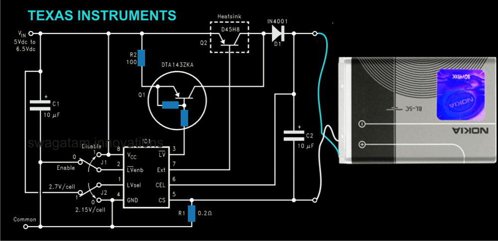
Design#3: Another Efficient Charger for Li-Ion using IC LM3622
Here we discus a current controlled Li-ion battery charger circuit which has been specifically designed for charging all types Li-Ion Batteries very safely and without any considerations.
It is generally advised that a Li-ion battery should be charged with utmost care and caution as these type of batteries are prone to instant damages or explosions if the specified charging measures are not employed.
Thanks to TEXAS INSTRUMENTS for providing us with this wonderful chip, the LM3622 which is an excellent Li-Ion charger, controller device.
How the Circuit Functions
The IC has been designed for generating a constant current at constant voltage, a basic prerequisite for all Li-Ion batteries. The IC may be configured for charging a single Li-Ion cell or a pack of many.
The circuit using the IC LM3622 can be fed with voltages right from 5 to 24V depending upon the charging needs and the connected battery.
The IC does not require any precision external resistors for implementing the functions. Moreover, the IC has a negligible drain of less than 200nA of current from the battery in the absence of an input voltage.
The in built circuitry of the chip accurately regulates the charging current through the principle of temperature compensated band-gap reference.
The current is regulated, however its done via an external current sensing resistor.The band gap principle results in an efficient operating control performance of the circuit and also of the input supply voltage.
The shown current controlled Li-Ion battery charger circuit illustrates a low drop out linear Li-Ion battery charger design which is capable of charging a single 3.7V Li-Ion Cell.
For enabling low voltage detection, the switches J1 and J2 may be appropriately selected.The IC starts the charging process by first detecting the voltage of the cell and “enable status” of the low voltage detection.
The transistor Q2 immediately comes into the operating condition as soon as the connected battery hits target regulation level, determined by the internal setting of the IC.Q2 now begins supplying a regulated voltage to the connected battery, initiating a constant voltage charging mode of the circuit.
In the above situation the battery receives a constant regulated voltage across its terminals, while the charging current is monitored depending upon the level of charge over the battery. On reaching a full charge condition, the charge current to the battery is significantly reduced to a safe value.
Smart Li-Ion Battery Charger Circuit Diagram using IC LM3622
These were the assorted top 3 smart, intelligent Li-Ion Battery charger circuits for you, if you any more ideas or information regrading such smart designs, please feel free to express them through comments.

Comments
Hi Sir,
Pls. help me. I need to charge LI-In Battery (48Volt single Cell/50 Amp).
Need circuit diagram with universal AC input and DC output of 50DC/50Amp with Battery Voltahge monitor, cuts-off the Primary when Battery is fully charged.
Thanks in advance.
Joshi
Hi sir I need help regarding TP4056 circuit board which i am using to make my circuit of connecting 3v dc motor to OUT terminal of the board and 18650 1000mah batter to battery terminal. When battery is connected to the circuit motor power ON and runs where as when battery is removed from the circuit it doesn't run the motor and a boost is required by connecting back the battery in circuit So can you plz help me to fix this issue to run the motor even when battery is not in circuit. The second issue is as the motor is of 3V it getting high voltage around 4v than the normal 3v so can that be fixed.
Thanks
Hi Siraj, you cannot have 0V at pin#5, otherwise the IC will go into a sleep mode…as suggested in the following instruction:
"VIN is the power supply input for the internal circuit to operate. Any time VIN falls at around 30mv below the BAT pin voltage, TP4056 goes into low power sleep mode, reducing BAT pin’s current below 2uA."
By the way why do you want to connect a motor with this IC, it is recommended only for charging a battery not for any other purpose…
how to use 4056 ic with automatic emergency led touch light
Hi Fayyaz, if the heat is little then there's nothing to worry, it could be due to your 3000mAH battery which may be trying to pull current over 1200mAH from the IC.
Thanks sir working fine but pcb heats up little bit battery is 3000 mah
SIR
HOW TO USE THIS CIRCUIT WITH AUTOMATIC EMERGENCY LED TORCH CIRCUIT
Fayyaz, use the above circuit in between the supply input and the LED circuit….make sure the input is a fixed 5V.
please sir help me to cross check this circuit and tell me if there is mistake in it ?? 3.bp.blogspot.com/-_UdjHmMHQv0/UFH_g8yEScI/AAAAAAAAAAk/ryA0wD3BxjY/s1600/12v%2Binverter%2Bdiagram.JPG
It has serious faults and if the inverter is made as per the diagram it will never work