In this article I have explained a VLF receiver circuit used for detecting insect wing beat signals, the idea was investigated and built by Mr. Steven Chiverton.
Insect Wing Triggered ELF
An incredibly fascinating electrical outcome successfully identified with the VLF are wing sounds triggered when bugs like bees, flies, and mosquitoes fly within a few feet of the VLF whip antenna.
The ensuing signal is a buzzing noise nearly the same as what may be listened to by ear, in spite of this, this impact is brought on by electrostatic releases every time the insect's wings flap.
It can be considered that electrostatic charges (static electricity) are amassed on the insect's wings then simply thrown out through each wing whip, producing a "modulated" electrical field around the pest at the identical frequency as the wings whisk.
Big insects, along the lines of wasps, Yellow jackets, Bumblebees and honeybees, render notably powerful buzzing sounds in the headphones-easily heard once those insect fly within 4 feet (1 meter) of the VLF antenna.
Mosquito Wing Beats
High-pitched Mosquito wing beat noises is generally noticed the smaller bugs within a couple of inches of the VLF Receiver's whip antenna.
Particular types of flies as well as other pesky insects possess considerably more electrostatic "buzz" out of them compared to other forms - Bees and Horse Flies, in our findings, include the loudest "buzz" in the earphones!
This might likewise have something connected with the structure of the insect's wing, with specific form of bug wings higher susceptible to static electricity build up and ensuing discharge.
There could be insect physical electrical releases produced within the insect's wing muscle tissues that help cause this , although not much is recognized concerning this occurrence.
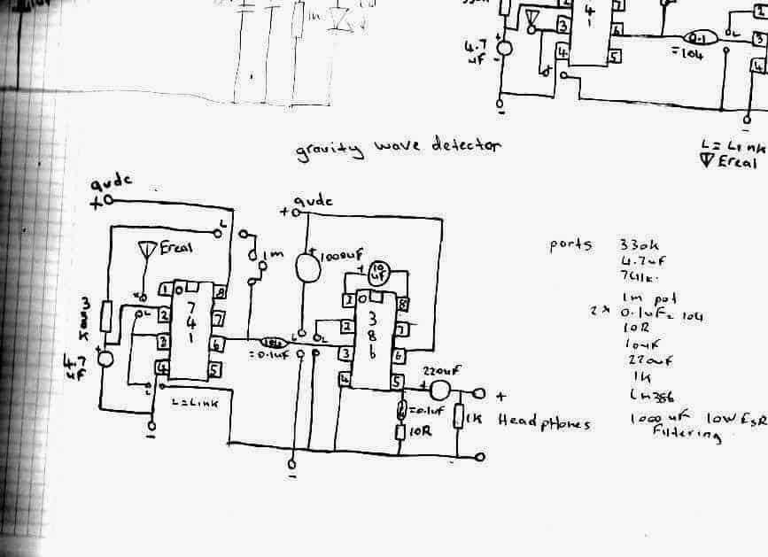
I've listened to sound recordings like whistlers etc and not one of these sounds matches the recordings I've collected from what I've received on my gravity wave detectors,
Detecting UFO Sounds
I'm working on 2 new VLF receiver circuits to receive these mystery VLF signals whether they be UFOs , there’s no info on these signals and there relation to UFOs if there’s one,
But I recall stories of people who hear low humming noises coming from UFOs , it’s a very low frequency signal itself and maybe if it uses ac it also covers, the VLF band of frequencies to, anyhow the iron peaces I need to make the core to concentrate the electromagnetic flux has been discontinued at dick smith electronics even though its in there catalog.
But I have enough in my collection to make one flux concentrator for the sensor coil
That fits the closest to the inside circumference of the plastic spool the coil is around.
I'll try jay car electronics to see if they have the same sizes I need for the next planed VLF sensor circuit,
Without the core to concentrate the electromagnetic flux, the signal reception is week but when you put a peace of the core into the centre of the coil the sensitivity jumps more and even more when you sit another core peace on top of the first one
These core peaces can be covered in heat shrink tubing to make it all hold together to form a single looking long core.
I have a number of the pieces so far but they are barrel shaped , so ill have to build the core with all these peaces , and hopefully jay car will have them to so I can construct the second core , for the other circuit to .
If you have read the top bit I to have received buzzing noises from fly’s but with one of my most sensitive gravity wave detectors and it has no areal just a sensor capacitor.
My latest VLF receiver tests have changed when I solder new 9 volts battery snaps into it now it was then more sensitive to the ac mains and recently I made a new lid for the VLF receiver circuit and had to resolder the wires to new leds I put into it now the circuit appears to be less sensitive to the ac hum as its lower as if the circuit is filtering it down or attenuating itself, but it still picks up the ticks from my watch at a good distance.
Using Zero Point Energy
I brought a few DVDs on ebay one called Tesla hunt for zero point energy and the other about Nazi flying saucers how they work something you cant get here so ebay was the place to order them on,
I've brought a number of emf detectors before to, off e bay but one seems to be really good but have got no ufos or ghosts with it and its sensitive but no ghost then to test it on but the one that's the k2 emf detector registers near the fridge here but nothing else that is ac powered gives a reading as if the ghost I saw last night likes to hide inside the fridge hehehehe
Anyhow, I've recently built a new insect gravity wave detector I copied it from my first old design which to my surprise senses insect wing signals from only stripped bodied flies which there isn't any here so far as the whether isn't to good
When I took my old design out and built a neon from it I discovered why it worked so well I mistakenly used pin 8 as the positive input and not pin 7 so I discussed it with Dave dede and he built it and got some bizarre results to and even more as pin 8 is not used on the 741
But Dave found a circuit on the Internet a Chinese one and in the circuit drawing they also used pin 8 for reasons we don't know cant speak Chinese heheh but a little looking around I find pin 8 also has another purpose
I forgot what it is but listed as something else other than just nc so anyhow I fired up my new circuit and even though the only 2 flies that flew by didn't have stripes on them and were to far away to register
Detecting Remote AC Hum
I noticed that the extra sensitivity is very interesting what are they really hiding and why is pin 8 doing things unheard of or not said so I sat outside with the detector on top of an outdoor table and I noticed that when I run my finger on the wooden part of the table the wooden slats that make the top of it I can hear it through my headphones strange
Even more bizarre is the unusual sensitivity to ac fields I bring the detector inside and with my bare feet on the ground
I can hear the ac mains hum but it goes away when I lift my feet off the ground as if the underground power here is absorbed into my body and re radiated so the detector can hear it again now I still have my old insect gravity wave detector design here
I'm using on it and the new one, 2x 9 volts batteries and they are due to be replaced as these nmh rechargeable may have had there days as one keeps loosing power.


Comments
Sir engineer Swagatam
I am working on a dog repellent circuit using a 40106 IC in conjunction with H-bridge transistors. Currently, the circuit oscillates at a single frequency with a 1000 picofarad capacitor connected between pin 1 and ground, and a 39k ohm resistor connected between pins 1 and 2 of the 40106. I’m interested in achieving variable frequencies for this circuit. Could you please advise on methods to adjust the oscillation frequency? Thank you very much in advance
Moe
Thank you Moe,
However can you please post this question under the following article, it will make your question perfectly relevant wit the article topic.
Once posted I will try my best to solve it for you…
https://www.homemade-circuits.com/dog-barking-preventer-circuit/
Dear Sir Swagatam
Please excuse me for leaving comment here since the reply button is not seen for May 11, 2024.
I trust this letter finds you well.
I have successfully resolved the issue of dropping the voltage to below 12V by applying nine 1.5V batteries instead of eight. When I switched on the circuit, the multimeter showed 11.8V. I then tested the circuit near a friendly cat at the silent park of the morning, at a distance of about 5 meters. Each time I switched on the circuit, the cat would run away and then return to me, may be it was hungry. After repeating this process a few times, I concluded that the circuit is working well. Unfortunately, I did not see a dog, but I am confident that the circuit is powerful enough to deter them as well. Additionally, I tested your proposed circuit and discovered that my piezoelectric is burnt, so I will need to purchase a new one.
I will never forget your kindness and the time you dedicated to helping me solve this problem. I am grateful for your assistance and for all the electronic tips I have learned from you. Thank you, dear Swagatam, for being a true symbol of a kind and generous person.
With warmest regards
Sincerely,
Emad
Please ignore my previous and publish this one.
Thank you so much Dear Emad,
That’s a great progress, I hope it works for dogs also.
Can you please repeat and post this comment under the following article:
https://www.homemade-circuits.com/dog-barking-preventer-circuit/
Because the above article is more relevant to our current discussion.
I have replaced the commenting system to default for better site SEO, therefore there may be some differences in its working. No worries, if you don’t find the reply button, you can always start a new thread.
Also, please note that once you reply it may not be visible in the article immediately, rather will be visible after 3 days, because of server caching…kindly bear with me for this inconvenience. Longer Caching helps my site to load faster.
Hope to hear from you soon…
Dear Sir Swagatam
Hello, I did as per your instruction. You are right Sir that article is more relevant.
I will let you know of my test with dogs also.
Best regards
Emad
No problem, dear Emad.
All the best to you.
Thank you Dear Emad, I appreciate your hard work and efforts to make this project successfull.
I think you give this circuit a try instead, because it produces an intermittent frequency pulses which can be more disturbing for a dog.
https://www.homemade-circuits.com/wp-content/uploads/2023/02/rat-repellent-circuit-pulsed-768×358.jpg
Let me know what you think about it…
Dear Sir Swagatam
I hope this message finds you well.
Thank you very much for the helpful article and your valuable response. I followed your recommendation and replaced the existing transducer with the one labeled AT3527 ( https://www.homemade-circuits.com/wp-content/uploads/2020/02/piezo-transducer.jpg ).
After powering on the circuit, I only heard a single knocking sound around 15 kHz. In comparison, the original transducer produces a continuous, sharp whistle at the same frequency.
I believe it might be best to retest the circuit under more suitable weather conditions and inform you of the results afterward.
I will also try your proposed circiut design. would it be possible to operate it using a 9-volt battery?
Your generous assistance is truly humbling. Thank you so much.
Sincerely,
Emad
Thank you dear Emad,
Imagine what happens when you make a hissing, or squeaking sound from your mouth near a dog, you will get a quick response from the dog and dog will look at you. So if the dog gets attracted even with manually created sounds then the dog should get attracted by a similar sound from a machine also.
You can an related information from this article:
https://en.wikipedia.org/wiki/Dog_whistle
If the dog is not getting disturbed by the sound from your device that means the sound is not entering the dog’s ear, or maybe it is not powerful enough.
Yes, I think you should try changing the transducer. If possible you can also try modifying the circuit into a pulsed form, as given in the following diagram:
https://www.homemade-circuits.com/wp-content/uploads/2023/02/rat-repellent-circuit-pulsed.jpg
Let me know what you think about it.
Dear Sir Swagatam
Hello.
Thank you very much for your comprehensive response. Thanks to your explanation, I now understand that the settings I configured were indeed correct. I wouldn’t have been able to achieve this without your assistance.
You are right, I did the test when the weather was windy. However, I am surprised why it did not effect even when I was very close to one of the the dogs.
For your information, I used eight 1.5V Duracell Alkaline batteries, and when I turn the circuit on, the voltage drops to 11 volts. could this be another reason of not effecting?
Sincerely,
Emad
Dear Emad,
On daytime in a park, there can be a lot of other noises and frequencies which could be preventing your frequency from reaching the dog’s ear. You will have to test it in perfect silence, only then it might show any effect.
However, since you have connected a powerful transducer in your circuit but you may be using a small 9V battery, that might not allow the transducer to produce any effective sound.
So I think either you must use a 27 mm piezo as the transducer or use a powerful lead acid battery for the existing transducer.
For the 27mm piezo, it must be housed inside a proper encloser such as the following one:
https://www.homemade-circuits.com/wp-content/uploads/2020/02/piezo-transducer.jpg
Let me know your opinion on this.
Dear Sir Swagatam
Hello. I hope this letter finds you well.
I placed a 20k Pot instead of R1 (this value was 1k in the circuit, as you are aware), used a 4.7k resistor for R2, and a 0.0033 uF capacitor istead of C1. Based on these values, the frequencies should range between 15 and 38 kHz according to calculations from the Ohmslascalculater website.
I tested the circuit in a park where there were Dogs and Cats, with different frequencies and unfortunately, it had no effect on them.
Is there a reason for that Dear Swagatam?
with warmest regards
Thank you Dear Emad,
The effect of the output frequency on animals will need to be tested and verified practically, with some trial and error.
Mostly, animals like dogs and cats are deterred by frequencies above 25 kHz.
Let me know if you have any further questions or doubts.
Dear Sir Swagatam
Hello. Thank you very much for introducing the ohmslawcalculater.com. It is very interesting.
I have a question regarding the choice of capacitors Sir. If I choose a capacitor of 2000 or 6800 picoFarads, will it have any effect on the output sound of the transducer that will be heard by the animals?
With warmest regards
Emad
No problem Dear Emad, I am always happy to help.
There are two resistors in a 555 astable circuit R1 and R2, both must be configured appropriately, along with a capacitor C1.
I would recommend you to refer to the following 555 astable calculator and then setup the circuit details as given in the article:
https://ohmslawcalculator.com/555-astable-calculator
You can use a pot in place of R1 with a series resistor such as 4.7k, without a series resistor there may be a risk of the IC 555 getting damaged, while adjusting the pot.
Let me know how it goes.
Dear Sir Swagatam
Thank you for providing such a wonderful online frequency calculating software and for your valuable response. It appears that both my inquiries and your patience are boundless. Men like you are very rare in this world. God bless you.
For a 20kHz frequency with a10nF capacitor, the software calculated a resistor value of 7.2 K; and for a 40 kHz frequency it provided a value of 3.6K.
would it be accurate to use a 10k potentiometer in conjunction with a 3.9k resistor, rather than fixed resistor values to determine the correct deterrent frequency?
With best wishes
Emad
Thank you Dear Emad,
I will try to answer your questions.
100k pot controls the pulse width or the PWM output
The 1k resistor and the capacitor together decide the frequency of the output.
You can adjust the above 1k and the capacitor values to set the frequency.
However, the PWM diodes and the pot can make the calculations difficult, so according to me you can remove the diodes and the pot and convert the circuit into a normal 555 astable circuit, and then calculate the frequency using any online IC 555 astable calculator.
Let me know if you any further confusions or doubts.
Dear Sir Swagatam
I appreciate your kind words. In fact, it was you who patiently assisted me in solving the problem. Thank you so much again.
I replaced the left TIP35 with a new one. Now it becomes less hot, a little more than the right one. My letter was long and I think you missed my question.
1. Is it correct that the 100k pot. affects the output frequency?
2. Could you please let me know how much should be the value of the capacitor in order to have an output more than 20kHz, now that I do not have an oscilloscope? I am so eager to see the working of the circuit in repelling the Animals.
I eagerly wait for your kind reply
With warmest regards
Emad
That’s great news dear Emad,
I appreciate your patience and hard work to solve this problem.
However, operating the transducer at a low frequency where it produces the knocking sound is not recommended, since it may cause the transducer or the transistors to get damaged.
If 3 transistors are cooler and only transistor is still heating up, then you can try replacing that specific transistor and check the results, most probably that particular transistor might have gone faulty.
Also, make sure you are using a supply voltage not exceeding 12V.
Let me know if you have any further questions.
Hello, dear Sir Swagatam
I trust this letter finds you well.
Following your guidance, I removed the transistors and connected the previous LED configuration directly across pin 3 of the two ICs. Even then, one LED remained continuously on. Replacing the left NE555, however, resulted in both LEDs exhibiting the desired blinking behavior. This outcome is particularly gratifying, and I suspect the initial malfunction arose from damage sustained by the replaced NE555 during previous tests which caused you a lot of trouble. Please accept my sincerest apologies for any inconvenience this have caused.
Your unwavering support throughout this troubleshooting process has been invaluable, and I’m thrilled to report that the circuit is finally functional. I don’t know how to thank you enough.
I reassembled the circuit with TIP transistors, four 200-ohm resistors, and one 1-kilohm resistor connected to pin 7 of the left NE555. Further tests yielded the following observations:
1. Blinking of the LEDs commences for capacitor value of 2.2 microfarads. When I connect the transducer, it produces a knocking sound. This knocking sound continued with other capacitor values like 10 or 22 microfarads.
2. From 1500 picoFarads upwards, the transducer generates whistles with varying tones.
3. After 25 seconds, the left TIP35 became so hot that I had to remove my finger. The other three transistors were warm after 25 seconds. Is there a reason for this?
My main question is: how can I set the circuit at 20 kHz without an oscilloscope?
Thank you so very much for your continued assistance.
Sincerely
Emad
Dear Emad,
If one LED is continuously ON then it is not good.
However this circuit is a tested design from a reputed website.
https://www.homemade-circuits.com/wp-content/uploads/2024/05/dog-baarkinng-preventor.jpg
Can you please remove the transistors and connect the previous LED configuration directly across the pin#3 to pin#3 of the two iCs.
This will show whether the IC configuration is OK or not.
Let me know it goes.
Dear Sir Swagatam
I hope this letter finds you well.
I followed your instruction just now. When I connected the circuit to the power supply without the capacitor, the green LED turned on and stayed on. However, when I each time added a capacitor to the circuit, the red LED turned on and the duration for which the red LED stayed on depended on the capacitance of the capacitor. For instance, when I connected a capacitor of 220 microfarad to the circuit, the red LED remained on for 7 seconds, causing the green LED turn off. After 7 seconds, the green LED remained constantly on without any blinking.
When I decreased the capacitance to less than 1 microfarad, the red LED quickly flashed and turned off while the green LED remained on.
Thank you a lot for your guidance and the diagram which you drew for me.
He who never forgets your kindness
Emad
Thank you Dear Emad,
You can connect the test LEDs in the following way:
https://www.homemade-circuits.com/wp-content/uploads/2024/05/LED-test-connections-to-H-bridge.jpg
After this, reduce the 555 frequency to 1 Hz or 0.5 Hz and check whether the LEDs blink alternately or not?
If it does then your H bridge circuit is working good.
Dear Sir Swagatam
Thank you very much for your response to my question about the pictures I had sent in your email.
I apologize if I misunderstood your instructions. Were you suggesting that I should connect the two ends of the 1k resistors (with the other ends already connected to the green and red LEDs) to the emitters of the TIP transistors?
Best regards
Emad
Thank you Dear Emad,
You had previously tested the same circuit with red/green LEDs and you saw the LEDs blinking alternately at a lower frequency.
This indicates that the 555 circuit is working correctly in a push pull manner.
You can confirm it again by replacing the transducer with red/green LEDs (connected with opposite polarities.)
Make sure to have a 1k resistor connected in series with each LED.
The images that you sent in my email are of 40kHz transducer, transmitter/receiver pair, which are used in ultrasonic proximity detectors.
Please let me know if you have any further questions, and do update the results.
Dear Sir Swagatam
Hello, I hope you are healthy.
I followed your instructions and increased the value of the 10nF capacitor to 1000nF in 10nF increments (adding 10nF each time). I then replaced the final 1000nF capacitor with the following values: 1uF, 2.2uF, 3.3uF, 4.7uF, 22uF, 47uF, 100uF, 220uF, and 470uF. Subsequently, I reduced the value of this capacitor to: 1000pF, 1500pF, 2000pF, 2200pF, 2400pF, 2700pF, 3000pF, 3300pF, 4700pF, 5000pF, 6000pF, and 6800pF. Unfortunately, I did not hear a buzzing sound from the transducer after these adjustments.
Based on your last response, I understand that this project may need to be set aside and a new circuit explored.
I would appreciate any further instructions you may have. Additionally, if possible, could you please let me know about the name of the pictures I sent to your email address?
Thank you very much for your continued support and assistance.
With warmest regards,
Emad
Dear Emad,
Please remove the diodes and revert the circuit to its previous form.
We have already confirmed that without the load (transducer) the transistors do not heat up.
Please confirm this once again with the TIP35/TIP36 transistors.
Once confirmed, reconnect the transducer, and reduce the frequency to maybe 5kHz by increasing the value of the 10nF capacitor, and check whether you are able to hear a loud buzzing sound from the transducer or not.
If your transistor don’t heat up without load and if you are able to hear the frequency at 5 kHz with load, that would confirm that your circuit is working perfectly alright.
After this, you can play with the frequency to determine the most effective frequency for your application.
Dear Sir Swagatam,
Hello
I recently replaced the left TIP36 of the last circuit test with a new one, though it had not heated up a lot. After soldering two pairs of 1N4007 diodes in series, I connected the positive poles of those diodes to the emitters of the TIP35Cs and the negative poles to the emitters of the TIP36Cs transistors. Upon powering up the circuit, the right TIP35C began to heat up. After 35 seconds, it became so hot that I had to remove my finger from it. The left TIP36C was cooler at that moment, but it was also heating up. Simultaneously, the diodes across the emitters of the left transistors became very hot after 10 seconds. The other two diodes and transistors remained cool, as if they were not functioning. The current being used by the transducer was 700mA.
I then disconnected the four diodes and connected the emitters of the transistors to each other as per the circuit diagram. The same issue occurred. The right TIP35 heated up again, and I had to remove my finger after 25 seconds. The left TIP36 was getting hotter, and the current being used by the transducer increased to 900mA.
It appears that the circuit is operational, but it requires two heat sinks, one for the upper and one for the lower transistors. I am hoping that using 8 1.5V alkaline batteries will provide enough current to capture a good video for my instructor, Sir Swagatam.
Additionally, a seller presented me with two components that he was unsure of whether they were transducers/receivers. Since I have not come across these components before, I have sent you pictures of them to your Email address. I kindly request that you help me identify them.
Please apologize me that I am still puzzled as to why the other two transistors have not shown any signs of functioning yet. I eagerly await your further instructions.
Thank you for your assistance.
Sincerely,
Emad
Thank you Dear Emad,
TIP36 is rated to handle 25 amps, so 50mA should not cause any heating at all, unless something is wrong with the conduction of the h-bridge.
Please add a 1N4007 diode in series with the emitters of the TIP35 transistors, and check the response.
If possible add two 1N40007 diodes in series with each TIP35 emitters.
This will help to generate some sort of deadtime between the conduction of the two arms of the H-bridge.
Please try this and let me know if it helps to keep the transistor cool.
Dear Sir Swagatam
Hello. I hope this letter finds you well.
I tested the circuit using TIP35C and TIP36C transistors with a 12V power supply and that high power transducer. This time, only the left TIP36C became hot, though not as fast as the BD680 did previously. I swapped the positions of the two TIP36Cs, but the left one still heated up. Rotating the knob of the 100K potentiometer did not produce any change.
The speaker draws 50mA of current but produces no sound, which is expected as humans cannot hear frequencies above 20kHz.
Awaiting your further instructions,
Sincerely,
Emad
Thank you so very much for your response I will certainly share the result; by piezo buzzer or a low current transducer.
Thanks again for your assistance and favor.
God bless you
scincerely,
Emad
No problem Dear Emad,
All the best to you. Please keep up the good work…
Thank you Dear Emad,
I understand your concern.
However, transistors do not consume any power, they are just like ON/OFF switches. They only decide the amount of power they can deliver to the load.
It is the load which consumes all the power.
So in your case, it’s the transducer that will consume all the power, not the transistors.
If you do not want to have a longer range then you can use a low power 27mm peizo buzzer transducer, as suggested by AI.
Dear Sir Swagatam
Hello. You’re absolutely right Sir. It would be worth watching. But the problem is that 2N3055 or TIP35 Transistors consume a lot of power and would require a larger battery. The truth is that, as a hiker who goes out every week, I need something compact and lightweight to deter stray dogs and foxes on the trails and it would be ideal if the circuit were powered by one or two small 9V Alkaline batteries.
AI suggested using piezoelectric speakers instead, but it did not mention what should be the suitable diameter of the P.E. speaker. Can you please confirm if AI recommendation is correct and wether the sound generated by a P.E. will only be heard by animals.
Thank you very much in advance for your response.
Best regards
Emad
Thank you Dear Emad, for updating the results..
Actually the series capacitor is specifically intended to reduce current, so i am afraid the transducer will not be able to generate high power output.
If you want your transducer to generate high power output then you may have to replace the existing transistors with TIP35 (2nos) and TIP36 (2nos)
Alternatively you can also try TIP3055 and TIP2955 transistors.
https://www.st.com/resource/en/datasheet/tip2955.pdf
This will allow high wattage, high range output from the transducer.
The base resistors can be around 200 ohms 2 watt or 1 watt.
Make sure to set the frequency above 15 kHz for optimal effect.
If it works then a video recording of it would be worth watching!
Dear Sir Swagatam
Hello. Hope you are fine
I decided to to get non polarized 10uf capacitor today, which I remembered that I could link two 22uF electrolytic capacitors with reversed positive and negative terminals to create a non-polar one. I did so and transistors remained cool after connecting the circuit to transducer.
Thank you very much Sir.
Just a question dear Swagatam: Can you confirm if this method generates sufficient output current to repel Dogs from 10 meters away now that we have power transistors within the circuit, Also this 10uf transistor? Or should I consider seeking a low-current transducer, which may pose challenges to find?
I will certainly record a video of working of it for you.
Thank you so very much for all your assistance and favor.
He who will never forgets your kindness
Emad
That’s great Emad,
That confirms it is your transducer which is causing the over loading and heating of the transistors.
I saw your email images, and it looks like your transducer is a high wattage device with high current requirement.
In that case I would recommended you using a capacitor in series with one of the wires of the transducer.
The capacitor can be a 10uF capacitor and must be non-polar type.
You are most welcome Emad, and i appreciate your interest to learn electronics with persistent hard work.
My dear instructor, Sir Swagatam
As soon as I connected the transducer, the previous two transistors became hot. I measured the resistance of the transducer with a Multimeter, and it showed 8 ohms. I have attached a photo of the transducer to your email. I would be very glad if you Could please confirm if this component is indeed a transducer, as the seller claimed.
I am always immensely grateful for your assistance and teaching me how the circuit works. Your kindness and continued support are always deeply appreciated.
Thank you for your time and consideration.
Sincerely,
Emad
Dear Emad,
That’s good! It means your transistors are not faulty, so the problem could be with the transducers.
Please connect the transducer and check again. This will confirm whether the transducer is causing the overloading and heating of the transistors or not.
The transistors are configured in H-bridge configuration, where the transistors conduct diagonally at any instant.
So for example, when left 555 pin3 is high and right 555 pin3 is low, the left BD679 and the right BD680 will conduct.
Likewise, when the right 555 pin3 is high and left 555 pin3 is low, the right BD679 and the left BD680 will conduct.
So as you can see the transistors conduct diagonally, so that the load is activated in a forward-reverse manner.
However, this also means that the load now gets a AC voltage, so it must be non polar.
Dear Sir Swagatam
Hello.
I’m writing to you to share some news. Today, I purchased four new transistors and assembled the circuit. I connected it to 12V power supply without a load, and thankfully, non of four transistors didn’t even get warm. I then proceeded to take voltage readings of the four transistors, and the results are as follows:
Left BD679 and Right BD680: BC=12V, CE=12V, BE=0V
Left BD680 and right BD679: BC,CE, and BE = 0V
I then swapped the positions of the BD679 transistors and repeated the process with the BD680 transistors, with the same result: only transistors left BD679 and right BD680 had voltage as follows:
Left BD679 and Right BD680: BC=12V, CE=12V, BE=0V
I’m curious why the other two transistors aren’t receiving voltage and I am sure you dear have some insights into this.
I truly appreciate your support and guidance.
Best regards
Emad
Dear Emad,
Please make the same previous circuit, but without any load. That means the place where the motor is connected will be now empty:
https://www.homemade-circuits.com/wp-content/uploads/2024/04/555-motor-reverse-forward-circuit.jpg
The capacitor and resistor can be of any value, we can fix that afterwards. First it is important to see whether the transistors become hot or not without the load.
Thank you so much dear Sir Swagatam for your kind response. Do you mean that I should reassemble your first circuit components without four no of 1k resistors? Also, d o I place 100k resistor across 1N4148 Diodes and +12V, and 10uf capacitor instead od 10nf?
Thank you in advance for your kind response
Best regards
Emad
Thank you so much Dear Emad, for your kind words.
Ok, so the red/green LEDs are blinking alternately, that means the 555 circuit is working correctly.
Now, you can configure the transistors back in the circuit, and check whether it is still heating up or not without any load connected.
Do not connect LEDs or transducer, and check if the transistors are still heating up not not.
If not, then connect the transducer and check again.
Dear Sir Swagatam
Hello. Your big favor in drawing the recent circuit diagram for me is beyond my expectation and is highly appreciated. You are the symbol of a real man and my words are too weak to express my feelings in this regard. Please apologize me.
The circuit is working well and blinking time of each LED changes by rotating the 100K pot.
Waiting for your new instructions, I remain
Sincerely yours
Emad
Hello Emad, the last reply from me might not have reached your email because you had made an error in writing your email ID, instead of gmail you wrote gamail.
I have corrected the ID so now you can follow this notification and reach this article to check your previous comment reply.
I am extremely sorry dear Emad, for the confusion.
Yes, the motor was in my diagram but it was supposed to be replaced with a transducer in your application.
Please initially try the following modified test circuit, this will prove whether the IC 555 circuit is working correctly or not:
https://www.homemade-circuits.com/wp-content/uploads/2024/04/555-push-pull-circuit.jpg
Dear Sir Swagatam
I hope this letter finds you well
I apologize that I was confused by the word “motor” in your recent response. While I did see the motor symbol at first glance in your recent (last month’s) circuit diagram, the similarity between the two circuits:
https://www.homemade-circuits.com/wp-content/uploads/2023/11/dog-repellent-circuit.jpghttps://www.homemade-circuits.com/wp-content/uploads/2023/11/dog-repellent-circuit.jpg
led me to believe that I was mistaken and that the real component is an ultrasonic transducer, mistakenly represented by a motor symbol in the circuit.
For reference, you can find the Cat and Dog repellent circuit diagram I mentioned previously (with the ultrasonic transducer) fifteen comments above.
Therefore, I used an ultrasonic transducer in place of the motor in your recent circuit. Please let me know if this was incorrect.
Best regards
Emad
Dear Emad,
Please remove the motor and replace it with two LEDs connected in parallel. Connect the two LEDs with their polarity reversed, and make sure to connect a 1k series resistor with each LED.
Now check the circuit. The LEDs must flash alternately.
Also, check now if the transistors still heat up or not.
Dear Sir Swagatam
Hello. Let me thank you first for mentioning the resistor values. I added 4 nos. of 1k resistors to the circuit and this time these two transistors became hot even faster than previous time that I tested the circuit without resistors: left BD680 and right BD679. I do not know what to say.
Thank you so much for your kindness and assistance.
Best regards
Emad
Sorry Emad, I forgot to mention the resistor values. They can be 1k 1/4 watt resistors…