In an IC 4047 astable oscillator circuit, the output of the IC continuously generates a switching ON/OFF signal. Since the output is never in a stable state and constantly switches between and low and high, it is called an astable multivibrator.
The astable ON/OFF switching frequency is adjustable and can be varied by changing the values of the RC network of the circuit.
In a 4047 monostable configuration, the output of the IC generates a single momentary switch ON pulse in response to a brief trigger pulse at the input pin.
The momentary ON output pulse is adjustable and can be varied by modifying the values of the RC network of the circuit.
The 4047 CMOS IC is specifically designed to be used as an astable or monostable multivibrator. We will first learn the working of an astable mode using this IC, and later on understand the different monostable operating modes and their configurations.
4047 Astable
The first figure below demonstrates the IC 4047 rigged in the true gating astable mode, where the circuit begins oscillating as soon as a high gate signal input is detected, whereas the oscillation quickly ceases when this input signal is rendered low.
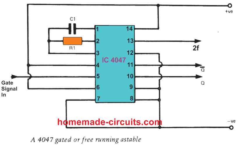
When the IC is required to run in a free running astable mode, the very same standard 4047 astable circuit becomes applicable, although in this case the pin#5 of the IC 4047 must be hooked up to the positive supply line.
In this mode the IC 4047 is able to generate an anti-phase oscillating outputs across its Q and "not Q" pinouts.
This feature turns the IC into a handy device for applications in which a pair of anti-phase clock signal outputs are mandatory.
When the input gated supply turns low or switches OFF, causes the Q output of the IC to go low while the not Q output of the IC is turned high.
There also exists a third output in the form of pin#13 of the IC 4047 and from this pinout we get an output signal whose frequency is two times (2f) more than the frequencies generated across the primary Q and "not Q" pinouts.
The waveform across all the above three outputs of 4047 is a an ideal squarewave. Each single output waveform cycle can be calculated through the equation
T = 4.4RC seconds.
The output frequency of the IC can be determined using the equation
f = 1/4.4RC Hz
Timing components R1 and C1 of the IC, are configured discretely using an external resistor and capacitor.
R1 can be selected to have any value between 10k to 1M, while the capacitor Cl can have any value above 100pF.
However, make sure that capacitor C1 is not a polarized capacitor, and its maximum value is recommended to be below 2.2uF.
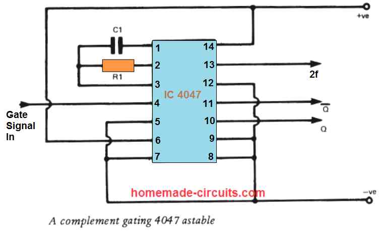
Complement Gating
The 4047 can also work as an astable multivibrator with a complement gating. In this configuration the circuit is disabled by applying a high gate signal and it is enabled as soon as the gate signal is turned low.
The IC 4047 complement gating astable circuit can be witnessed in the following figure.
4047 Monostable
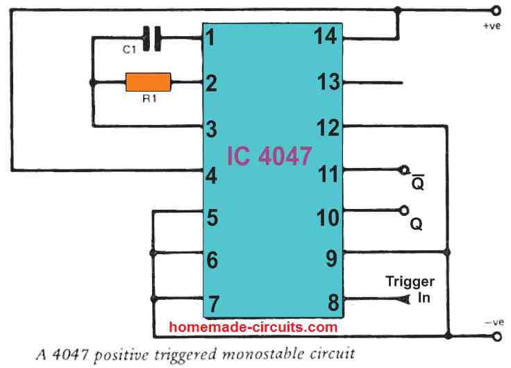
The 4047 CMOS IC works extremely well in the monostable multivibrator configuration and also in the astable mode. There can be 3 monostable configurations in which IC 4047 can be used: positive triggered, negative triggered, and retriggerable.
In the positive triggered method, the triggering is executed through a low logic turning into a high logic.
The negative triggering is implemented in the opposite way by applying an input logic that starts from a high state to a low state.
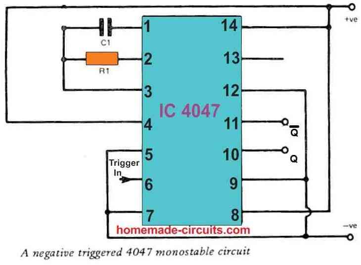
In both the above modes, the output pulse shuts off after the specified time interval lapses, regardless of whether the input is still in the triggering state or not.
The retriggerable type differs in terms of this action from the previous two modes, and similar to a 555 monostable, the output pulse in the retriggerable mode does not shut off as long as the input trigger pulse persists.
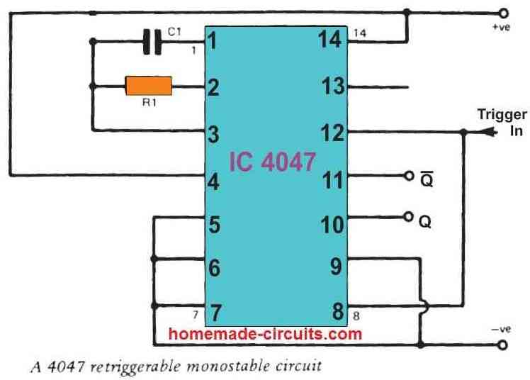
The 4047 retriggerable monostable circuit is triggered with a positive edge pulse, to be precise. In all the above three configurations the output pulse duration is at a level determined by 2.48 RC seconds, where R1 is recommended to be between 10k and IM.
Timing capacitor C1 for the monostable circuits can be of any value higher than 1nF, but it should be strictly a polarized type.
In all the three variants the Q output is initially at low logic and it turns high to generate a positive output pulse, while the "not Q" output is initially high and provides a negative output pulse.
Comments
/home/jarel/Escritorio/zschematic.gif
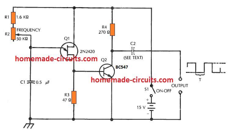
Hi. Could you please tell me the formula for the attached circuit, the result of which is 30kHz ?
Thank you very much.
Capacity – 1 microfarad (The capacitor is not an electrolytic capacitor!)
Resistor – 13440 Ohm (If you want to get the exact 30.00 Hz frequency, you will have to make a compound resistor!)
With these components we get the exact frequency 30.00 Hz
I have been a long time visitor of your site, and I had a question not specifically related to the circuit discussed above, but more of a question about electronics in general. How did you learn to understand and design circuits? I’m just a teen trying to learn that cant afford formal education in this area and was wondering if you had any resources or books that you would recommend to someone trying to gain a better understanding of electronics as a whole?
You can learn by building small electronic projects, by understanding the concepts stage wise, and then slowly learn how to combine those smaller projects to make bigger projects. It might take many years of practical and theoretical learning until you finally grasp the procedures.
Presently I do not have any references which can help a beginner to learn circuit designing quickly, however I may post a related article soon in this blog.
will 12-0-12 work on the inverter effectively as expected