In this post we try to diagnose a burnt SMPS circuit and try to troubleshoot and repair the circuit. The shown unit is a cheap readymade Chinese make SMPS circuit. This article is written as per the request made by Mr. Kesava.
My SMPS got Burnt
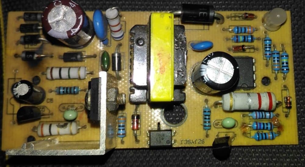
The below attachment is 12v 1.3 amps SMPS for charging Agriculture Sprayer..If charge full the green led will glow...If charge low the red led will glow...
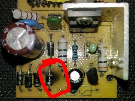
But now this charge not working...And i check inside , The AC input bridge rectifier IN4007 1diode got damaged...i replace it with new one diode..Now the new diode also damaged....Pls guide me sir....
In our area shop..this type of chargers are not available sir...But my aim is not to buy new one..i itself want to rectify with u r guidance sir....Pls help me sir....
Sorry for bad english.I'm not good sir...
Thanks & Regards N.Kesavaraj
Troubleshooting the Problem
Hi Kesava,
It's most probably due to a burnt mosfet, the one which can be seen on a heatsink. You can try replacing it with a new one, and also make sure to change the adjoining 10 ohm resistor which also looks like it is burnt.
Regards.
Repairing the SMPS Circuit
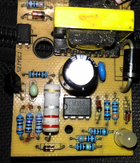
Referring to the images above, the primary side of the unit appears to be the popular 1 amp 12V SMPS adaptor using a mosfet based switching design, and includes an opamp based auto cut off charger section at its secondary section of the board
From the first two images we can clearly see that one of the diodes being completely blown apart, and responsible for shutting down the entire circuit board.
A bridge rectifier can be normally seen at the beginning of any SMPS circuit and is introduced primarily for rectifying the mains AC to a full wave DC, which is further filtered using a filter capacitor and applied to the mosfet/inductor stage for the intended flyback primary side switching operation.
This primary side switching causes an equivalent low voltage pulsating DC to be induced at the secondary side of the transformer, which is then smoothed using a large value filter capacitor at the the secondary side for acquiring the final stepped down SMPS DC output.
From the image it appears that the entire design is based on a mosfet, inductor switching topology wherein the mosfet becomes the main switching element in the circuit.
The diodes in the bridge rectifier appears to be the normal 1N4007 diodes which are capable of handling not more than 1 amp current, therefore if this 1 amp value exceeds the diodes can get ripped through and damaged.
The diode might have burnt due to a high current passage which in turn might have happened due to a stalled mofet inductor operation. Which means that the mosfet might have stopped osculating causing a short circuit through itself, allowing the entire AC to go through the components within the input supply line.
How to Repair the SMPS Circuit.
The shown burnt SMPS can be repaired with the following simple steps.
1) Remove the mosfet from the PCB and check it with a multimeter
2) Without any doubt you will find the mosfet being the faulty component, so you can quickly go for a replacement of the same using a correctly matched mosfet
3) After changing the mosfet make sure to change the burnt rectifier diode also, and ideally change all the 4 diodes in the bridge, to ensure no weakened diodes are present in the network.
4) You may also want to check if there are any other parts such as resistors or thermistor that may look suspicious and if any replace them with new ones.
5) Once all the doubtful elements are replaced it is time to switch ON the SMPS for the final verification.
However this must be done with a series protection load in the form of a series incandescent bulb to make sure that the circuit does not blow of due to some other hidden fault. A 25 watt bulb will be just good for safeguarding the unit from any catastrophic circumstances.
6) On switching on the SMPS, if the the bulb does not glow, it would probably indicate all's well and the unit has been repaired successfully. Now you can feel free to check the output voltage of the SMPS with a meter and confirm that it is producing the right readings.
7) Finally without removing the bulb connect an appropriately rated DC load and check whether it is working correctly or not.
8) If everything seems to be working normally you can remove the series bulb, and repeat the testing process, but make sure to include a small fuse in series with the input supply permanently.
9) However in case the bulb shows a bright glow, would indicate a serious problem persisting in the SMPS circuit and will need to be investigated afresh, this may be done by first switching off the unit and then checking each and every component in the primary side of the trafanformer.
10) The components which needing a recheck will be fundamentally the ones which are prone to high voltage and current damage, such as small BJTs, diodes and low value resistors.
11) The components which can be left unchecked are the ones which are adequately rated and are able to protect itself from from high voltage and current inrush. These may include high value resistors above 50K, or low value wirewound resistors above 1K.
Similarly, capacitors which may be rated above 200V can be left unchecked unless one of these look somewhat damaged externally.
Testing for a Burnt Inductor Transformer
Every SMPS circuit will essentially include a small ferrite transformer, which this part can also possibly become the cause of a burnt SMPS circuit, although the chances of a damaged transformer can be too remote.
This is because the wires inside the inductor might require some time to burn, and before this can transpire the other more vulnerable parts such as diodes and transistors would be forced to blow off ,preventing any further damage to the inductor.
So basically you can be rest assured that the transformer is the one element which might be the safest and the undamaged part in a given faulty SMPS circuit.
If in a rare event the inductor burns, this would be distinctly visible from the burnt insulation tape which may be also melted and stuck with the winding. An SMPS with a burnt transformer could be virtually irreparable, because a burnt transformer would mean most of the elements burnt out, along with PCB tracks uprooted. Time to buy a new SMPS unit.
The secondary side mostly will not require any checking as it is isolated from the primary and can be expected to be aloof from the dangers.
Well, this concludes this article explaining tips to repair an SMPS circuit, if you think I have missed some crucial points, or if you have something important to add in the list, please tell us through your valuable comments.
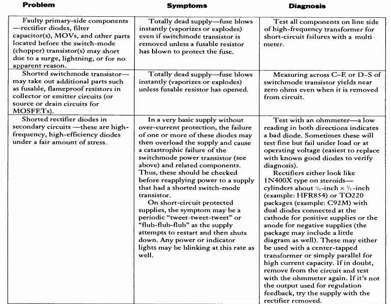
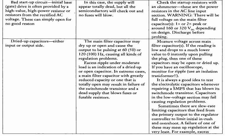
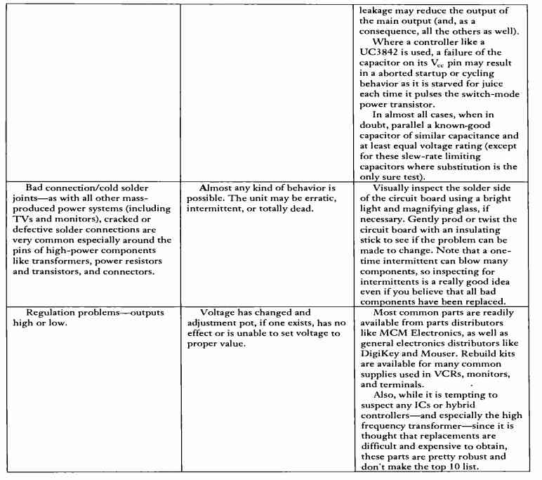
More Tips and Solutions to Repair SMPS can be studied in the following table:

Comments
hi,
I have assembled a DIY SMPS with a 24V, 20A rating. It is a self-oscillating circuit that utilizes the IC TL494 and features a short-circuit and overload protection circuit using the LM358.
I got the output voltage of 24V without a load. But as I connected a 24V lamp, the voltage across the lamp dropped to 6V, and the lamp was faintly lit.
It seems the circuit does not deliver the necessary amperes. What could be the reason, and where to check for the fault? Please help.
Hi, did you calculate the transformer accurately, because transformer is the key component in any SMPS circuit and it requires critical design considerations.
Also, the wire gauge is important, which decides the current for the secondary side of the transformer. You can checkk out the following for estimating the wire gauge of the transformer.
https://www.homemade-circuits.com/56492-2/
Please let me know if you have any further doubts regrading this subject
Hi Swagatam;
My SMPS battery charger specs.: input 220AC and output 88V DC and 8A (750W).
There was a big wattage and smal value resistor but burnt at the input side which was placed between the bridge rectifier (- pole) and the mosfet source leg. I removed it and replaced with the 2,2 Ohm 5W resistor. I would like to know that if this resistor value can affect the output current or not?
P.S.: There is a dummy resistor 4K7 Ohm at the output capacitor and the 88V output voltage is OK at the present.
Hi Suat,
that could be a current sensing resistor which is responsible for controlling the maximum output current output.
You can measure the output current by using different values for this resistor and check whether the output current is correspondingly varying or not.
The dummy load resistor looks Ok to me, although it could be a 10k also for lower current dissipation.
Hi Mr Swagatam;
I tested my scrap smps battery charger (88,5V 8,5A). The electrical mini car battery (totally 6 pcs of batteries serial connected) value was about 80V before the charging process. The current consumption was about 160 mA while the charger was connected. Now I am not sure that this so small amount / low current value is normal since the battery is saturated (80V) or the the test is failed? So I need your opinion about the matter.
Hi Suat,
Is 80V the full charge specification of your series connected batteries? If yes then the current consumption is ok, if not then the current is too low.
Hello,
These questions may sound very stupid, but I am a beginner in SMPS repairs and after reading your above article and the correspondence in the comments section, I thought you might be the right person to ask for help. I would like to set up a bench for testing and repairing SMPS. Can you please give me a list of basic tools that I will need? Is an Oscilloscope a must? what should be the specifications of the Oscilloscope if it is a must.
Hello Ketan, an oscilloscope is good but not a compulsory tool required for repairing SMPS.
You can easily repair SMPS units using a digital multimeter and a frequency meter.
Always connect a 40 watt or 60 watt incandescent bub in series with the AC supply while troubleshooting an SMPS, and also take the necessary safety precautions, since an SMPS is not isolated from 220V AC mains supply.
However if you want use an oscilloscope you can get the following type of oscilloscope which will do the job nicely:
https://www.homemade-circuits.com/dso138-best-small-oscilloscope-for-electronic-hobbyists/
Hi Mr. Swagatam;
SMPS as the battery charger for the 88,5V output. I can adjust the output voltage by trimming the TL431 resistor (R2) and its value about the 5K. The voltage to be divided is the output voltage as 88,5V and the primer resistor is about 10K / R1 for the divider circuit. Could you please tell that the minumum R1 value should be? Because I would like to gain lowest voltage value at the output.
Hi Suat, I think the following article can help you to calculate the values of the required resistor, or you can tell me which circuit best suits your requirement, then i will try to calculate it for you:
https://www.homemade-circuits.com/explaining-programmable-shunt-regulator/
Please let me know…
Thanks Swagatam. I can adjust the output voltage at the moment. But I am not sure
about the minumum output capacity of the circuit? For instant would it let the 5V at the output or that is beyond the limitation of the circuit? Yes I am able to reduce the voltage by reducing the resistor value between the cathode and refence legs of the TL431 however my concern is that if I would use just 10 ohm resistor here does this defect the circuit or not? If the circuit will let me have the for instant about 30V output voltage so I can test it with the double 12V batteries since it is problem for me to find 6 pcs batteries.
As a result that is not big problem thanks again for your kind interest.
Hi Suat, 10 ohm resistor could burn the TL431, so I would not recommend that, instead there should be another resistor with this resistor forming a potential divider, associated with the ground side, you can try altering that and check the response!
Hi Mr. Swagatam;
I am going to issue a video about the smps circuit at the youtube and if you do not mind I would like to mention about your page since I have received your support? And if it would be issued then I could inform you about that.
Thank you Suat, that would be great!
Please let me know when you have published the video on youtube…
Hi Mr Swagatam,
My SMPS is input 220V and output 88,5V. I can see the 88,5V at the output after the repair. However I see about 300V DC after the bridge diodes on my multimeter display. And I see the below value on my oscilloscope dispaly while it is set to 10x 100V 50ms DC Auto.
All of the Mın Max AVG VP and ARMS value = 716V and VPP OmV.
here I need your help since the multimeter reads the voltage as 300V. This means there is a loss about 20V on the circuit or no problem?
P.S. : There is no load but dummy load as 4k7 is on at the output.
Hi Suat,
220V is the RMS value, and its peak value after the bridge network should be around 220 * 1.41 = 310V, so 300V looks Ok to me, it is nothing to worry about.
Hi Mr. Swagatam;
I need to test my battery charger (input 220AC output DC 88,5V 8,5A)
The circuit has 10K pot resistor at the output (you had called it as dummy load) Is it possible to swap that resistor with the 5W 4K7 stone resistor.
To test it I will use 6x12V = 72V accumulators in a very short period. I think the output is OK due that there is constant 88V at the output, although there is a dummy load
10K resistor at the output.
could you please advise any temporarily measurement that I can apply before this test in order to protect the circuit? Or I have nothing but try and see?
Hi Suat, yes a 4.7k 5 watt should work as a temporary dummy load.
But a 10k pot does not look like a dummy load, if you tell me its configuration then I may be able to identify its exact role in the power supply.
If your battery Ah rating is above 50 Ah, then there’s no harm in trying charging the battery directly with the power supply for a short period of time, with an ammeter in series.
thanks Swagatam;
Sorry I misleaded you since the former dummy load resistor was burnt so I had temporarily changed it with the 10K pot.
No problem Suat, thanks for the clarification, i hope you have left the wiper arm of the pot open.
The feedback is my pleasure and duty. At the moment before your latest message I had removed the pot and placed the 5W 4K7 stone resistor and at present no problem seems at the output voltage. Then my only concern is about the mosfet IRFP460 at the primer side if it will handle the initial current or not.
Ok great, glad it is working fine. IRFP460 should easily handle 8 amps since it is rated to handle a maximum of 20 amps..
THE BOOT SWITCH WILL NOT WORK
My SMPS 250W on the CPU. The LED light continuously blinking’s and the boot switch will get ON work. However RAM point and CMOS are ok. The issue is after sometime, the Blinking light stops and solid light remains. At such stage, it can be boot and computer works fantastic. It seems when one component in the SMP gets properly energize with full voltage the booting works computer will work 24/7. But upon shutting off the CPU & UPS over night, same issue occurs. Which component may it be in the SMP that is getting defective.
It looks like a computer motherboard fault not an SMPS fault, according to me.
Sir, I ve changed the SMPS just now finally it has worked fantastic. as I ve mentioned in my first query, WHAT COMPONENT IN SMP CAUSE THE ISSUE MENTIONED THAT UPON COMPLETELY ENERGIZED TO THE REQUIRED VOLTAGE, NO PROBLEM TO BOOT AND ALL FUNCTIONALITY WORKS WONDERFULLY.
OK, great, thanks for updating! Without checking the SMPS practically it can be difficult to judge the fault.
Hi Mr Swagatam;
circuit specs.: input 220 AC output for 72V battery charge
error type : fluctuating high voltage (12V-130V) at the seconary side.
I have removed the octo-couplers and tested, both of them seem good. so I think there should be any failure at the primary side.
Is it possible to have your comment on the matter.
Hi Suat,
Opto coupler feedback stage are specifically used for stabilizing the output voltage to a fixed limit, so I am not able to figure why your circuit output voltage is not getting fixed using the opto coupler?
In that case the problem could be with the either IC or maybe the zener diode associated with the opto is malfunctioning
Thanks for the support, today I realized the disconnection between the IC and the mid pin of TL431. In other word there was soldering failure. I resoldered the TL431 and now voltage is stable.Regards
Thank you Suat for updating the info, Glad the problem is solved now…
Hi Mr Swagatam;
There are double optocoupler, a fast diode, utc358(dual opamp), 14 pins level leds driver and finally BT153 at the secondary side of the 72V battery charger.
The error type is : DC output capacitor voltage fluctuates between about 12V and 130V.(whereas expected about stationary 84V DC)
Is it possible to have your advice about that?
Hi Suat, is this happening with load or without load? It could mean that the IC is trying go into a shutdown mode.
I think the opto-coupler stage might be having problems, and not regulating the high output voltage situation correctly.
Hi Mr Swagatam;
If smps battery charger input is 220AC and output is 84V DC 8.5A(eight-point-five).
What shoud be the fuse value at the input side?
Hi Suat,
The fuse at the AC input side should be 84 x 8.5 / 220 = 3.24 amps
Swagatam is my favorite site for many many reasons, appreciate the founder efforts
Thank you so much Abdul, I am glad you found this site useful.
sir its 450w PC PSU zebronics ,I connected HDD data cable extensiom which caused short blow up 12 or 5v in HDD and made it not working but it’s fixed now, but at this time the other 2hdd was running and computer is on . so when searching I came to know about checking for short in cabls,I found out 3.3v 5v short with ground ,12v is ok , so when checking inside I found 51 ohm 31 ohm giving beep continuity , so I removed them , then checked for short , there was no short now, but replacing these resistors give back the same short, its a working PSU so I am not sure what to do next, I know this short is not normal ,I am not using this PSU now , pls guide me thank u , I will upload the pics in some time , those resistors were seats were blackened by the way
Sorry Megan, I am not sure about this issue, I am unable to figure out a solution, because I have never repaired a computer SMPS circuit.
https://ibb.co/2vwyb7g
https://ibb.co/BtvccmD
https://ibb.co/xq8vr6g
https://ibb.co/jJwkBWS
https://ibb.co/RPZH11j i have included the pics now, may be it could give some idea
Those links are not opening on my computer…..
“This site can’t be reached
The connection was reset.”
tired to upload in diferent site,pls check sir https://postimg.cc/MvPfkc50
https://postimg.cc/0bBjWT5c
https://postimg.cc/t1yj2k6B
https://postimg.cc/NLZZdbqR
https://postimg.cc/8fddB1gK
Extremely sorry, still can’t figure out the fault…it is difficult to troubleshoot the fault just by looking at the images, because there’s no way to understand the function of the resistors.
Sir our RO servicemen replaced switching power supply as fault and which was replaced 4 months before. Again now he says the same faulted and replaced another one with rs700 as charges.but i find the old one with no clear prints and sth written with sketch pen and it’s sides are affixed with cellphone tapes.i doubt could it b a new one or repaired one .Do a new piece have all these above identities .or he has cheated with old and repaired one tome.Also its print is unclearand found warrenty upto 12/2023.will u guide me of it pl
Hi duvarakanathan, I will have to see the image of the SMPS, without seeing it can be difficult for me to judge whether it is a brand new piece or an old repaired one.
However from your description it looks like it is an old repaired piece, not a new piece.
HI SIR I HAVE A SMPS (S-360-12) IT DOESNT TURN ON LED OFF ALSO AND WHEN I CHECK THE INSIDE THERE ARE NO BURNED? ANY SUGGESTION SIR?
Hi Jock, check the voltage across the bridge rectifier on the AC input side of the circuit? Check whether a 310V DC voltage is available or not?
Yes, if you know the number of the IC.
If we have fault in ic
Can it be replaced
Hi Ali, the fault can be identified only after the checking the SMPS board practically.