Accurately measuring very low currents of a few microamps or less using a regular panel meter or multimeter is not feasible. To make such precise measurements, you need to employ an active circuit, like the one depicted here.
This circuit low current ammeter circuit can be constructed as a self-contained unit or integrated into an instrument requiring a highly sensitive current range.
Range of the Low Current Meter
This specialized instrument is capable of measuring currents ranging from 100 nanoamps (10^-7 amps) to 10 mA at full scale, divided into six distinct ranges.
The inclusion of higher ranges serves the purpose of precise calibration, and they generally overlap with the lower current ranges found on many multimeters.
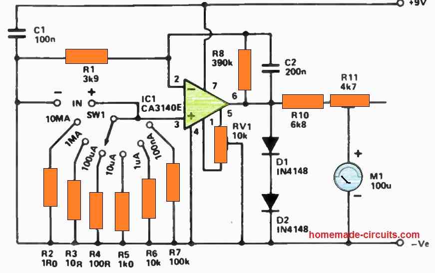
The meter, labeled M1, is a 100 µA movement connected in the fashion of a voltmeter with a full-scale deflection of 1 V.
The resistor components R10 and R11, the latter being a trimpot, act as multiplier resistors. The trimpot serves as a calibration control, fine-tuned to achieve full-scale meter deflection on the 10 mA or 1 mA ranges.
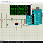
Circuit Diagram
How the Circuit Works
IC1 is an operational amplifier configured in the non-inverting mode with a DC voltage gain of approximately 100 times, determined by the feedback network formed by R8 and R1.
C2 is used to reduce the AC gain to near unity, enhancing stability and immunity to stray interference. The non-inverting input of IC1 is biased to the 0 V reference by the selected range resistor (R2-R7) as determined by SW1.
In theory, this setup yields zero output voltage and no meter deflection. However, in practice, it's necessary to compensate for small offset voltages using the offset null control, RV1.
Extremely low current from the circuit being measured flows into the input terminals of the instrument.
A voltage is developed across the chosen input resistor, one from the set of R2 to R7.
IC1 then amplifies this voltage, resulting in a positive meter deflection.
Consider the scenario where the 10 mA range is selected. The input current flows through R2.
If the input current is, for example, 5 mA, Ohm's law dictates that 5 mV will develop across R2:
E = I x R = 5 x 10^-3 x 1 = 5 mV.
Given IC1's gain of 100 (calculated as Gain = R8 / R1 = 390 x 10^3 / 3900 = 100), the voltage at pin 6 of IC1, with 5 mA input, will be 500 mV or half a volt.
Consequently, the meter will indicate half scale, yielding a reading of 5 mA. The successive ranges boost the instrument's sensitivity by a factor of 10.
This setup relies on the high input impedance of IC1 (a 3140), ensuring it doesn't "load" the selected input resistor and compromise reading accuracy by drawing substantial input current.
The 3140 is a FET-input op-amp with a typical input impedance of 1.5 million megohms. It's crucial to note that, for reasonable accuracy, all input resistors (R2 to R7) and op-amp feedback resistors should have a tolerance of 2% or better.
Meter Protection
Protection for the meter is ensured through the inclusion of D1 and D2. In cases where the input current surpasses the maximum allowable for the chosen range, the output voltage of IC1 will rise beyond 1 V.
If it exceeds approximately 1.2 V, both diodes will begin to conduct, effectively preventing any further increase in the output voltage of IC1.
This safeguard mechanism shields the meter from overloads that exceed 20% of the rated input.
Offset Null Adjustment
When making adjustments to the offset null control (RV1), start with the slider positioned at the end connected to pin 5 of IC1. Initially, the meter should display a pronounced deflection.
Gradually adjust RV1 backward just enough to bring the meter to a zero reading and no further.
How to Calibrate
Calibrating this unit can be accomplished using several methods.
A straightforward approach involves acquiring a variable power supply capable of delivering 10 V and obtaining a 10k resistor with a precision of 1% or 2%.
Additionally, you will require either a well-calibrated mirror-scale multimeter or a digital multimeter.
To begin calibration, connect the resistor and the low-current meter in series and attach them across the output of the power supply.
Simultaneously, connect the multimeter across the power supply's output, taking care to observe the polarities.
Select the 1 mA range on the low-current meter and an appropriate range on the multimeter. Gradually lower the power supply's output and activate it.
Adjust the power supply settings meticulously to achieve a precise 10 V reading on the multimeter.
During this process, carefully adjust R11 for a full-scale deflection. At this point, your low-current meter should be accurately calibrated.
If you replace the 10k resistor with a 1k resistor, having a precision of 1% or 2%, you can verify the calibration for the 10 mA range.
Another Simple Circuit for Measuring Extremely Low Currents
Introducing a novel circuit design that enables precise current measurements, even at extremely low levels.
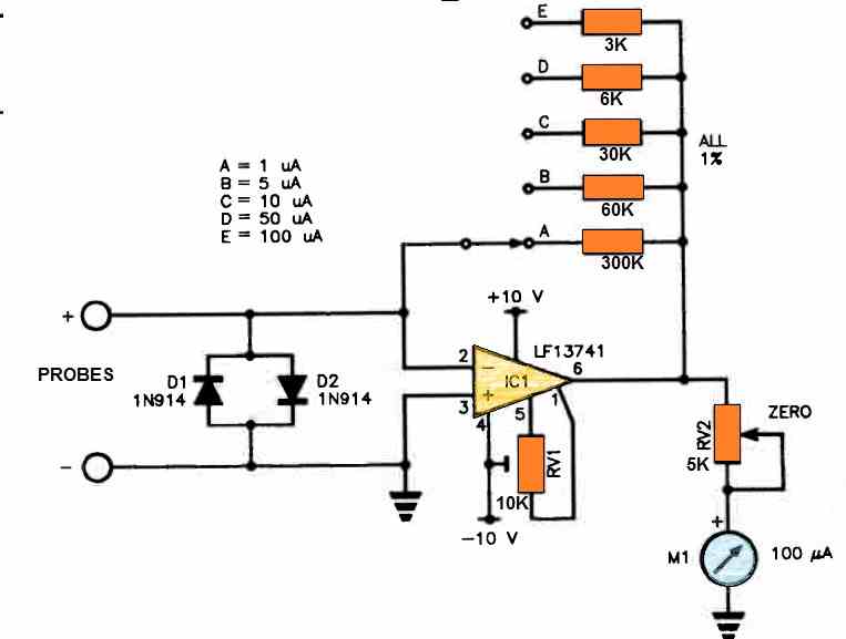
This innovative circuitry grants you the ability to effortlessly measure currents as minute as 100 nanoamps, thanks to its capability to gauge currents down to one microamp fullscale.
The foundation of this circuit lies in the utilization of a high-accuracy JFET-input operational amplifier known as LF13741, developed by National Semiconductor.
To establish the initial output offset null for the IC 741, RV1, a trimpot, is employed, which seldom requires adjustment.
Additionally, RV2 allows the full scale deflection adjustment of the meter.
The op-amp's amplification factor is determined by a switch, facilitating the attainment of the desired full-scale reading.
The role of the D1 and D2 diodes is to protect the circuit from excessive voltage dips. These diodes are used in the circuit to make sure that the input voltage drop does not go over 0.6 volts.
This voltage restriction offers some defense against any harm or instability that can be caused by greater voltage drops.

Comments
It’s ok to use LM741 instead of CA3140E?
Yes, 741 should also work according to me…
FYI in the above for the second circuit you state “Additionally, RV2 allows for meter zero calibration” in fact it is for setting the output reading on the meter with a known input. RV1 is the zero set resistor.