An efficiency of around 85 % and a power output of more than 200 watts is what you will get from the present design of a power inverter (home built). Complete circuit schematic and building procedure explained herein.
Introduction
You might have come across many articles regarding power inverters, however you might be still confused about making a power inverter? The present content provides a complete building tutorial of a home built power inverter.
If you are planning to make your own low cost and simple home built power inverter then probably you won’t find a better circuit than the present one.
This heavy duty, easy to build design includes very few numbers of components which can be found readily available in any electronic retailer shop.
The output of the inverter will be obviously a square wave and also load dependent. But these drawbacks won’t matter much as long as sophisticated electronic equipment are not operated with it and the output is not over loaded.
The big benefit of the present design is its simplicity, very low cost, high power output, 12 volt operation and low maintenance. Besides, once it is built, an instant start is pretty assured.
If at all any problem is encountered, troubleshooting won’t be a headache and may be traced within minutes. The efficiency of the system is also pretty high, in the vicinity of around 85% and the output power is above 200 watts.
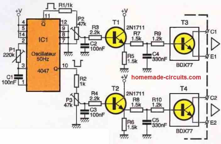
A simple two transistor astable multivibrator forms the main square wave generator. The signal is suitably amplified by two current amplifier medium power Darlington transistors.
This amplified square wave signal is further fed to the output stage comprising of parallel connected high power transistors. These transistors convert this signal into high current alternating pulses which is dumped into the secondary windings of the power transformer.
The induced voltage from the secondary to the primary winding, results a massive 230 or 120 volts conversion, as per transformer specifications.
Let’s study in details how the circuit functions.
Circuit Operation
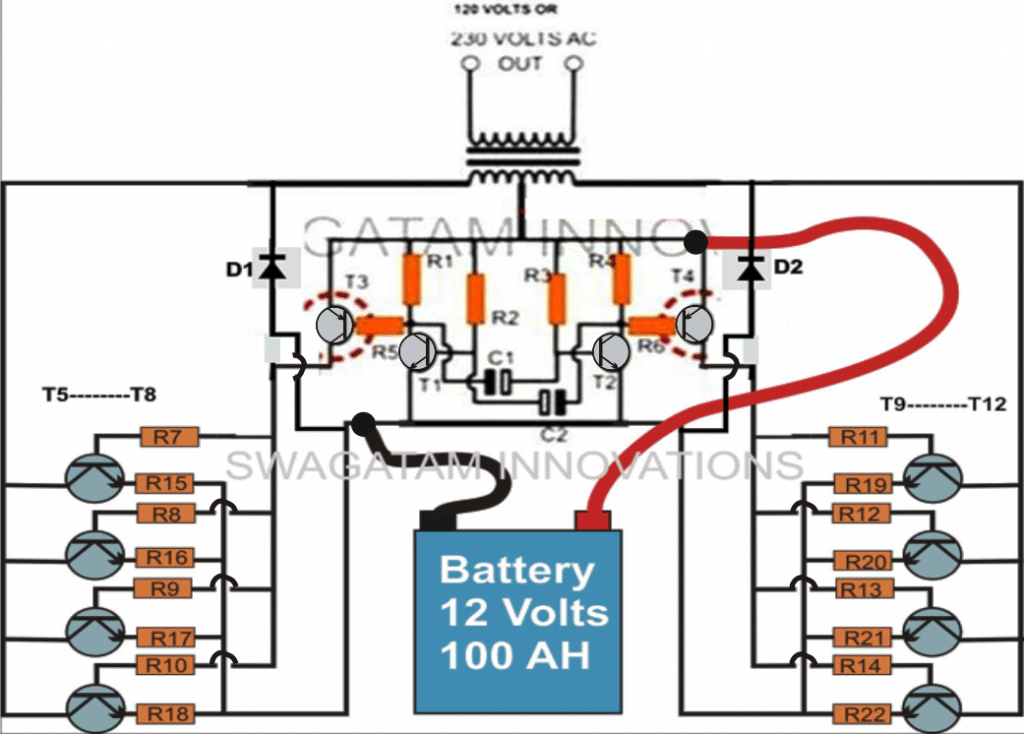
The circuit diagram description of this home built power inverter may be simply understood through the following points:
Transistor T1 and T2 along with C1 and C2 and the other associated parts forms the required astable multivibrator and heart of the circuit.
The relatively weak square wave signals generated at the collector of T1 and T2 is applied to the base of the driver transistors T2 and T3 respectively. These are specified as Darlington pairs and thus very effectively amplify the signals to suitable levels so that they may be fed to the high power output transistor configuration.
On receiving the signal from T2 and T3, all parallel output transistors saturate well enough according to the varying signal and create a huge push pull effect in the secondary windings on the power transformer. This alternate switching of the entire battery voltage through the windings induce massive step up power into the primary windings of the transformer producing the desired AC output.
The resistors placed at the emitter of the 2N3055 transistors are all 1 Ohm, 5 Watts and has been introduced to avoid thermal runaway situations with any of the transistors.
PARTS LIST
RESISTORS ¼ WATT, CFR
R1, R4 = 470 Ω,
R2, R3 = 39 K,
RESISTORS, 10 WATT, WIRE WOUND
R5, R6 = 100 Ω,
R7-----R14 = 15 Ω,
R15 ----R22 = 0.22 Ohms, 5 watt (can be connected directly if all the parallel transistors are mounted on a common heatsink, separate for each channel)
Capacitors
C1, C2 = 0.33 µF, 50 VOLTS, TANTALLUM,
Semiconductors
D1, D2 = 1N5408,
T1, T2 = BC547B,
T3, T4 = TIP 127,
T5-----T12 = 2N 3055 POWER TRANSISTORS,
Misc.
TRANSFORMER = 10 to 20 AMPS, 9 – 0 – 9 VOLTS,
HEATSINKS = LARGE FINNED TYPE,
BATTERY = 12 VOLT, 100 AH
Inverter Building Tutorial
The below given discussion should provide you with a detailed step wise explanation regarding how to build your own power inverter:
WARNING: The present circuit involves dangerous Alternating Currents, extreme Caution is advised.
The only part of the circuit which is probably difficult to procure is the transformer, because a 10 Amp rated transformer is not easily available in the market. In that case you can get two 5 Amp rated transformers (easily available) and connect their secondary taps in parallel.
Do not connect their primary in parallel; rather divide them as two separate outputs (See Image and Click to Enlarge).
Next difficult stage in the building procedure is the making of the heat sinks. I won’t recommend you to fabricate them by yourself as the task can be quite a tedious one and time consuming too. It would be rather a better idea to get them ready made. You will find variety of them, in different sizes in the market.
2N3055 Pinout Diagram
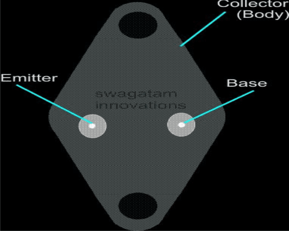
Select the suitable ones; make sure that the holes are appropriately drilled for the TO-3 package as shown in the figure. TO-3 is the code to recognize typically the dimensions of power transistors which are categorized in the type used in the present circuit i.e. for 2N3055.
Fix T5----T8 firmly over the heat sinks using 1/8 *1/2 screws, nuts and spring washers. You may use two separate heat sinks for the two sets of transistors or one single large heat sink. Do not forget to isolate the transistors from the heat sink with the help of mica isolation kit.
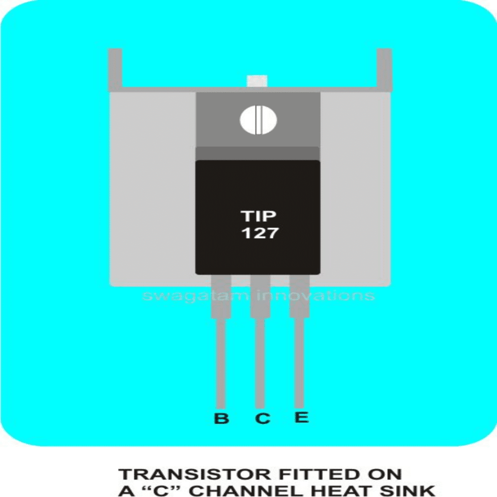
TIP127 Pinout Diagram
Constructing the PCB is just a matter of putting all the components in place and interconnecting their leads as per the given circuit schematic. It can be done simply over a piece of general PCB.
Transistors T3 and T4 also need heat sinks; a “C” channel type aluminum heat sink will do the job perfectly. This is can also be procured ready made as per the given size.
Now we can connect the relevant points from the assembled board to the power transistors fitted over the heat sinks. Take care of its base, emitter and the collector, a wrong connection would mean an instant damage of the particular device.
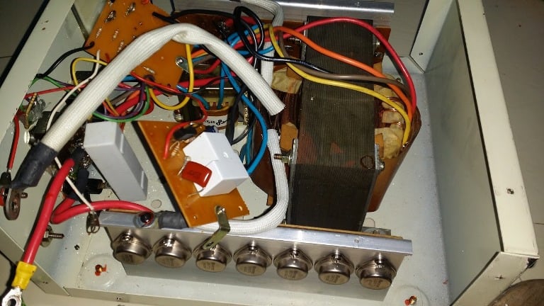
Once all the wires are connected appropriately to the required points, lift the whole assembly gently and place it on the base of a strong and sturdy metallic box. The size of the box should such that the assembly does not get crammed.
It goes without saying that the outputs and the inputs of circuit should be terminated into proper socket type of outlets, to make the external connections easy. The external fittings should also include a fuse holder, LEDs and a toggle switch.
How to Test
- Testing this home built inverter is very simple. It may be done in the following ways:
- Insert the specified fuse into the fuse holder.
- Connect a 120/230 volt 100 Watt incandescent lamp in the output socket,
- Now take a fully charged 12V/100Ah lead acid battery and connect its poles to the inverter supply terminals.
- If everything is connected as per the given schematic, the inverter should instantly start functioning illuminating the bulb very brightly.
- For your satisfaction you may check the current consumption of the unit through following the simple steps:
- Take a digital multimeter (DMM), select 20A current range in it.
- Remove the inverter fuse from its fuse holder,
- Clip the DMM’s prods into the fuse terminals such that the DMM’s positive prod links with the battery positive.
- Switch on the inverter, the consumed current will be instantly displayed over the DMM. If you multiply this current with the battery voltage i.e. by 12, the result will give you the consumed input power.
- Similarly, you may find the output consumed power through the above procedure (DMM set in the AC range). Here you will have to multiply the output current with the output voltage (120 or 230)
- By dividing output power by the input power and multiplying the result by 100, will immediately give you the efficiency of the inverter.
- If you have any questions regarding how to build your own power inverter, feel free to comment (comments need moderation, may take time to appear).


Comments (93)
Conectar 2 transformadores 12v.-10A.en serie respetando principio y fin de c/u.
Afectaría? funcionamiento….-gracias
If you connect 2, 12V transformers in series it will become a 24V transformer.
Good morning sir (Africa time)
ist possible to use EC42 800w to make 3kva inverter?
and it’s possible to use combined 3 transformer in parallel?
“Can I have a video explaining the circuit connection in detail? I’d be very thankful.”
Good Morning Klinton, if the transformer is rated to work with 800W then it cannot generate 3000 watts, not feasible.
Even with 3 in parallel you can get not more than 2200 watts, due to losses.
Mr. Swagatam good morning, a query: I want to build an inverter to run a 100w refrigerator and 2 computers, the question is: is a single inverter recommended to run the 3 appliances? Or an inverter for each device? And if it were a single inverter of how many watts would it be? And if the inverter would be for each device, how many W would it be each? And if it were an inverter for each device of how many AH would be the batteries, thank you very much for the answer you can give me, greetings from Lima Peru.
Hello Basilio, for any inverter it is recommended to have at least 25% higher power margin than the output load, meaning for a 100 watt load the inverter must be rated at around 125 to 150 watts. This rule is recommended for a single inverter and also for individual inverters.
Since the battery would be a lead acid battery, it must be discharged or charged at 10% of their Ah rating. Meaning, as an example a 40 Ah 12V battery when discharged at 3 or 4 amp rate would last for 10 hours ideally. Now 4 x 12 gives 60, which means the load can be a 48 watt load. Similarly a 12V 100 Ah battery when discharged at 10 amp rate would last for 10 hours. In this case the load could be a 12 x 10 = 120 watt load
Sir i need some information.
Single 12 -0- 12 5Amps transformer will give output? Or 5amps two transformer required? Because in my location 12-0-12 10amps transformer not available. Please confirm.
Shripad, a single transformer will produce 50 watts of output, and two in parallel as indicated in the above article will produce 50 + 50 watts.
Hi sir, thank you for wonderful circuit.
I have 12v 32ah battery and old ups transformer ( 2 wire transformer not center taped). Can i use this circuit?
Dear sir waiting for valuable reply.
Thank you Shripad for liking this post. Two wire transformer will not work for this inverter, you will need a 3 wire transformer, because a center tap wire is a must for this type of inverer circuit
Ok sir thank you…
Hi Swagatam,
supposed i add more of tr power until capable to run transformer of 5kva, it is big enough to run an aircon, induction cooker , refrigerator, washing machine and some other home aplication, but, is square wave safe to run aircon, induction cooker and washing machine which use motor inside them ? thanks in advanced,
cheers.
Lanny
Hi Lanny, no it is not safe to use square wave for aircon. I would recommend using the second circuit from the following article, instead, and upgrade its output section for more power appropriately:
https://www.homemade-circuits.com/modified-sine-wave-inverter-circuit-2/
Hi Swagatam,
Can I replace tr 2N3055 with IGBT? perhaps need optocopler? do you have the diagram too? thanks.
Yes that may be feasible, and opto coupler will not be required for this. make sure to add a 1k resistor across T3/T4 collectors and ground
Hi Swagatam, how can I decide to make 50Hz or 60Hz, by changing what parts? thanks
Hi Lanny, you can do it by altering the values of C1, C2 appropriately.
is the above circuit tested
hii sir
i need correct specification of transformer for making 200w inverter
as you say to connect transformer in parallel then we will get 2 output of 230 v or what
the circuit diagram of previous blog and this blog is different why?
If two transformers are used then they must be 12-01-12V 10 amps each, for single it should be 12-0-12V 20 amps
Inverters can be of many types and specifications yet with similar output range
sir swagatam am in need of a pure sine wave inverter circuit diagram using ferrite core transformer that can handle heavy load to run computer and refridgerator
Hi Jahridez, making a ferrite core inverter is never easy, yet you can refer to the following post which discusses one design which may interest you!
https://www.homemade-circuits.com/5kva-ferrite-core-inverter-circuit/
good day mr swagatam thanks much for your reply, in our country jamaica most of our appliances uses 110-115/60hz but some may supports 220volts, how would you design the driver output stage for 115/60hz instead of 220v/50hz i also have a stock of mosfet transistors 3205 and IC sg3525 can they both work in this diagram
Hi Jahridez, the output voltage in inverters is decided by the transformer secondary rating. For getting 115V you will need a transformer with a secondary rated at 220V.
Alternatively, if your existing transformer is rated at 12V/220V, in that case you can use a 6V battery instead of 12V, and still get 115V at the secondary without changing anything in the design.
okay swagatam well understood, what if am using a ferrite core transformer for my inverter project would it any difference to achieve getting the output to be 115volts or now i have to do less winding on the primary or secondary of ferrite transformer please note with thanks
okay swagatam i got that but as you understand more on those formulas as per given in data so that means i would have to half each windings to get my 110v of the world transformer is it both primary and secondary or which should i put the less turn on
Hi Jahridez, according to me the secondary side can be made lower for getting lower output, but this will need to be implemented through a proper ratio based formula.
you can find more details under this post:
https://www.homemade-circuits.com/how-to-design-and-calculate-ferrite-core-transformers-for-inverters/
Hi Jahridez, yes the principle is the same, it’s the winding ratio that will decide the voltage output in a ferrite core transformer also, but you will have to calculate it appropriately using specified formulas
Can I use C1 and C2 elctrolitic capacitor
yes you can, but 0.33uF is mostly non polar, unless it is a tantalum
Please give the value of R15. to. R 22
Vinod, you may connect the emitters directly with the ground if you use a common heatsink for the transistors on each channel. Meaning mount all the transistors from left channel on one common heatsink, and similarly mount all the right side transistors on a single common heatsink. Don’t use mica isolator for the transistors because since all their collectors need to be joined together so can be shorted through the heatsink
Sir, thank u for ur response.remain bless
how are u doing, sir pls is about the 200va square wave inverter my question is about the component u listed
1. resistors R1,R4,R3,R2 . U said is half watt, CEF
2.CAN U xplain what u mean by 10watt wire wound resistors and CEF as well
3. the trans4mer 5 amps what is the rating like u rated 10amps as 9-0-9volt
4. the xternal fittings should include a fuse holder, leds and atoggle switch, should this be connected at the output of the inverter ac pls xplain
1) Those are CFR type meaning carbon film resistors.
2) 10 watt is the power handling capacity of the resistor, wire wound means that these are not CFR based rather made by winding steel wires inside.
3) the 5 amps will be also 9-0-9V rated
4) the external fittings are optional, include them as per your preference…
Mmm in my country its difficult to access that and I think that might be an expensive device.
Ok I designed astable multibrator circuit but I don’t know the waveform so what can I do to know it
you must use an oscilloscope for that
Am interested with this page but am new in electronics I know little about it. Can I gate help here?
you can ask the questions, I’ll try to help
#sir which devices are work in this inverter?
#If fan will work how much hour?
#If I can use computer ups transformer?
#If I can increase wattage by adding transistor more?
#Any problem with square wave?
Thank you sir
All equipment will work with this inverter, but it is not recommended for sensitive electronic equipment because it is a square wave inverter.
computer transformer cab be tried.
you can increase wattage by adding more transistors
Hello sir pls what is the function of T3 and T4
T3, T4 amplify the oscillator current so that the output power BJTs can be driven optimally
Be patience with sir, i meant i want to modify or convert the same square wave circuit to sine wave by adding sg3525 to the circuit
SG3525 cannot be used for making a sine wave inverter, because it does not produce anything related to sine wave
Hello sir, pls where is the square wave output and the pwm output in the circuit
solomon, PWM is not there, only squarewave output is generated from the central Transistor stage
Pls explain more, which of the transistor
T1, T2 generate the square waves.
Ok, thanks, sir i want to use the same circuit to modify it to sine wave using ic sg3525 and some other components, please i need tutorial for that, or please i want you to design me the modified circuit using the same circuit. Thanks
Solomon, sorry I did not understand your requirement properly, which inverter do you intend make, the above one or by using a SG3525? and which one do you to be a sinewave?
Hello Sir, Pls How Can I Modify The Circuit To Sine Wave
I have already answered
Hello Sir, What Is The Maximum Power Of The Circuit
solomon, power will depend on how you select the specifications of the trafo, battery and the transistors….
Hello Sir, Pls I Have Some Question To Ask. 1. What Is The Maximum Power/wattage Of The Inverter, 2. Can I Reduce The Number Of Power Transistor And Use Low Capacity Battery? 3. Can I Change It To Sine Wave, If So, What Is The Suitable Component To Use Instead. Thanks
if you reduce the transistors then its power handling capacity will also decrease..for sine wave conversion you will have to implement the following concept:
https://www.homemade-circuits.com/2013/04/how-to-modify-square-wave-inverter-into.html
Do you mean that if my inverter battery is 12v i should replace it with 18v solar panel,?? and also if my inverter is 200 watt, the solar panel also must be 200 watt??
yes that's right!
Sir how do i change this inverter to solar inverter
replace the battery with a solar panel having voltage at least 6V higher than the inverter battery spec, and a couple of watts higher than the inverter transformer wattage.
Dear Swagatam Majumdar, I am Krishnaa – From Chennai.
If I use Two 10000MFD capacitors across 12-0-12 side of transformer What will happen?
Can we get smooth 230VAC waveform at output?
Please clarify, My Email ID is "krishnaa_m@hotmail.com"
Dear Krishnan, that won't help, instead you can connect both the the capacitors together right across the battery terminals, this will help to reduce harmonics and ripples within the circuit and ensure a much cleaner 220V output…however all these remedies will not keep the 230V constant because the 230V is directly dependent on the battery voltage which will keep dropping with time.
Hi,sir
what is the substitute for diode 1N5408
Hi Divya, you can try for any other similar 3 amp/1000V or 3 amp 300V diode….but according to me 1N5408 is the most standard and widely used part.
Sir ,
I read all blogs ,I have 12-0-12 transformer ,shall i used in your circuit ,it is 4 ams .how much load can be handel?
Thanx sir ,
I made it & works fine. 🙂
you are welcome Shrikant
For power transformer what is turns ratio?
you will have to get a made-to-order transformer, or use any standard 9-0-9V/220V/15amp step down transformer…making it at home can be difficult
Thanx for reply sir, can I use TIP3055 instead of 2N3055.& can I use two 7ah battery in parallel connection..
Hi Shrikant, yes you can use TIP3055 instead of 2N3055
can I use 12v 7ah battery for this inverter?
No you can't
Hey,
i have an 150ah lead aside battery and,one ups 600va e184736 transformer,can you please tell me what type of inverter circuit should i do?
Hello sir..
This is dipak i am confused here in charging system is they ckt charge battery automatically
hello dipak, no the above circuit will not charge the battery…the battery will need to be charged separately using a separate charger circuit
you can probably try the following circuit:
https://www.homemade-circuits.com/2015/05/simplest-pwm-modified-sine-wave.html
the parts list dose not mach circuit
a few questions, how are you connecting the power transistors to each other? then to each end of the transformer (1 wire to one set of 4 other wire to other set of 4) couldn't you just use the heat-sink aren't these npn power transistors? according to your symbol they are so all of their bodies are connected together. what do i search to get the correct transformer? i cant seem to find 12-0-12 10 amp to 220v ac unless this is a step down transformer in reverse? my only electrical shops are ebay or jaycar.com.au It's my first time using transformers. Lastly you said about the 1 ohm 5 watt at the emitters of the power transistors, are they 10 watts or 5 you said 5 at the intro but commented to someone 10 watts or does it no matter for this circuit?
great circuit otherwise just needed more info in its' description
great, wish you the best!
Thanks heaps! I've bought all the stuff now including heat sinks and case, all I need now is the transformer, it's proven difficult that they don't sell many 10 amp transformers in Australia and when I do find them they are $30+ :/
That's correct, all transistor collectors of the respective channels join together through the heatsink and connect with the relevant transformer outer taps.
As for the transformer, the winding rated 12V connects with the battery side that is with the 2N3055 collectors….while the 220V side becomes the output for operating the appliances.
Great! thanks for the extra info. So the heatsink can actually connect the 4 power transistors collector (body) to each other for the 2 sets and would this shock you if you touched the heat sink? that's probably why I can't find the right transformer. and to use a transformer in reverse; E.G. 240ac input 12V DC output would be connect battery to the 240ac input side and the 12V dc output side now becomes 220v ac? please let me know how to use it in reverse.
otherwise Great circuits, keep up the good work.
The transistors are connected as they are shown in the diagram, click the diagram to enlarge for getting a better view. one common heatsink is used for all the transistors on each channel, meaning two separate for the two channels, if a single common is used it would create a short circuit.
The emitter resistors make sure that the transistors conduct uniformly so that all dissipate evenly.
The wattage of the resistors will depend on the battery AH and transformer amp rating, if its above 40AH and 5amps respectively, the 2N3055 base/emitter resistors will need to be upgraded to 10 watts, for lower wattage a 5 watt would suffice.
Ideally a 9-0-9V/10amp transformer is required, and it'll be a step down type used in reverse for the inverter application
can this transformer work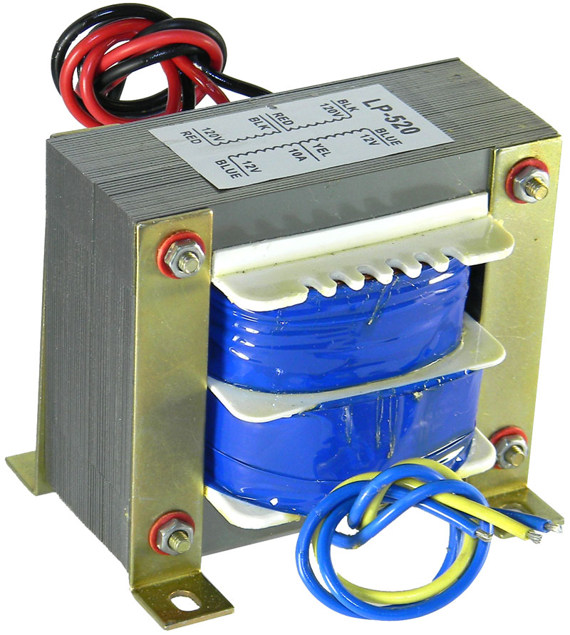
yes will do, but preferably it should be 9-0-9V, not 12-0-12V
can 0.47mf work 50 volt
yes will do, but make R2/R3 = 33K
I’m very happy to see you projects thank for this wonderful site
I’ve got a doubt I’ve seen some 8 pin transformers in inverter circuits whatis that how do i test it and know its ratings.
Thank you!
The pins could be the terminals corresponding to particular winding of the transformer. These winding could be connected with a particular inverter circuit for the intended specific safety functions and other similar things.