In this project I will show how to construct an air pollution meter using MQ-135 sensor and arduino. The pollution level in the air is indicated by series of 12 LED. If higher the number of LEDs glows, the higher the pollution content in the air and vice versa.
Overview
This project can prove very useful in places where air quality plays an important role such as in hospitals. Alternatively, this can be also another hobby project for your own home.
Although this we cannot expect a great degree of accuracy with this project, it can definitely give a reasonably good idea regarding the pollution level at your ambience.
The pollution in the air can be carbon dioxide, carbon monoxide, butane, methane, and some odourless gas. The sensor cannot differentiate between gases but, it takes all the gas samples from the air in a go.
If you are living in metropolitan city and you apartment is placed near a busy road, this project might come in handy to give a rough insight about air ambience.
Most people ignore the air quality measures at their residence, it is estimated that India alone contributes to 1.59 million deaths every year, which includes indoor and outdoor pollutions.
Majority of the population is unaware of air purifiers which are readily available on markets and e-commerce sites, which does not cost more than a smartphone.
Okay, now warnings apart, let’s dive into circuitry.
The Design:
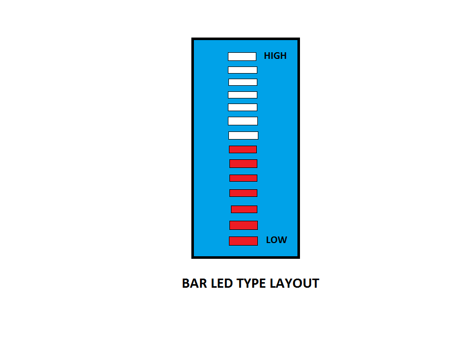
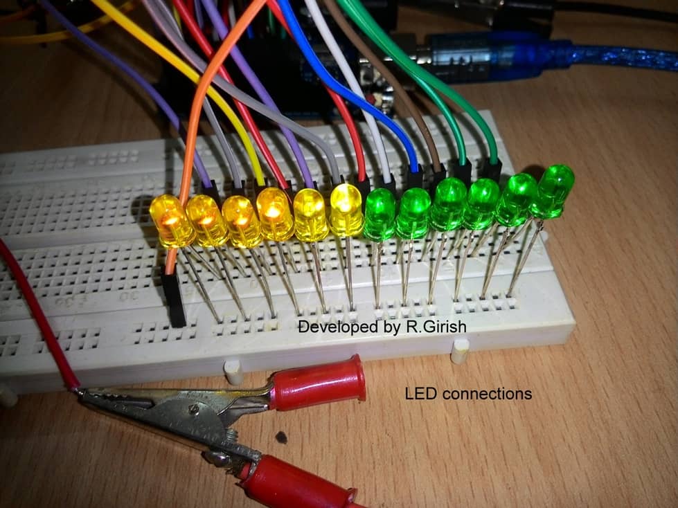
The air pollution meter will be more interesting if the LEDs are rectangular shaped and above layout design is used. However, you can use your imagination to make this project more interesting to you.
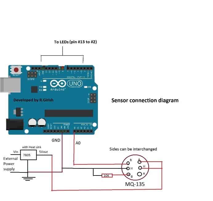
The above schematic illustrates, how to connect sensor to arduino. An external power supply is implemented for heater coil of the sensor. The sides of the sensor can be interchanged.
The pin A0 of arduino senses the voltage variations in the sensor due to changes in pollution content in air.
The sensor acts as variable resistor (in response to pollution) and 10K is fixed resistor, this act as a voltage divider. The arduino has 10-bit ADC, which helps the LED to glow discretely in response to air pollution level, which is an analogue function.
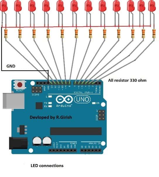
When the analogue voltage level crosses a certain threshold level which is pre-determined in the program, it will turn on LEDs.
The successive LEDs are pre-determined with higher threshold levels.
It starts with LED test, each LED is turned on sequentially with some delay and the user can determine the error in the LED connections, such as unconnected LEDs and LEDs which are not sorted sequentially. The program comes to halt for 5 minutes and all the LEDs glow simultaneously.
This will give enough time for the sensor to warm-up; we can see some of the action performed by arduino in serial monitor. Once sensor reaches optimum temperature, arduino sends some readings to serial monitor. Based on the readings, LEDs will turn ON and OFF. Higher the values print on serial monitor, more number of LEDs turns on.
The serial monitor is not mandatory in this project, but can be a handy tool for testing purposes.
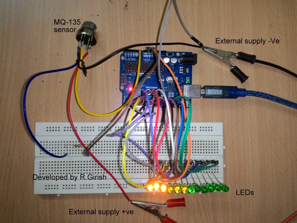
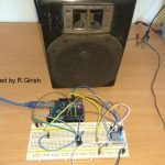
Prototype Image:
How to test:
• Turn on the arduino and external power supply. LED test will begin and it runs only once.
• The program waits for 5 minutes for sensor to get heated up.
• Once the readings shows up on serial monitor bring a cigar lighter and leak the gas without flaming it.
• Soon, the readings go peak and more number of LEDs starts to glow.
• Once you stop flow gas on the sensor, gradually LEDs turns off. Now your LED air pollution meter is ready to serve you room.
Program Code:
//--------------Program developed by R.Girish---------------//

int input=A0;

int a=2;

int b=3;

int c=4;

int d=5;

int e=6;

int f=7;

int g=8;

int h=9;

int i=10;

int j=11;

int k=12;

int l=13;

int T=750;

unsigned long X = 1000L;

unsigned long Y = X * 60;

unsigned long Z = Y * 5;

void setup()

{

Serial.begin(9600);

Serial.println("Sensor is getting ready, please wait for 5 min.");

pinMode(a,OUTPUT);

pinMode(b,OUTPUT);

pinMode(c,OUTPUT);

pinMode(d,OUTPUT);

pinMode(e,OUTPUT);

pinMode(f,OUTPUT);

pinMode(g,OUTPUT);

pinMode(h,OUTPUT);

pinMode(i,OUTPUT);

pinMode(j,OUTPUT);

pinMode(k,OUTPUT);

pinMode(l,OUTPUT);

pinMode(a,HIGH);

delay(T);

digitalWrite(a,HIGH);

delay(T);

digitalWrite(b,HIGH);

delay(T);

digitalWrite(c,HIGH);

delay(T);

digitalWrite(d,HIGH);

delay(T);

digitalWrite(e,HIGH);

delay(T);

digitalWrite(f,HIGH);

delay(T);

digitalWrite(g,HIGH);

delay(T);

digitalWrite(h,HIGH);

delay(T);

digitalWrite(i,HIGH);

delay(T);

digitalWrite(j,HIGH);

delay(T);

digitalWrite(k,HIGH);

delay(T);

digitalWrite(l,HIGH);

delay(T);

delay(Z);

}

void loop()

{

Serial.println(analogRead(input));

if(analogRead(input)>=85) digitalWrite(a,1);

if(analogRead(input)>=170) digitalWrite(b,1);

if(analogRead(input)>=255) digitalWrite(c,1);

if(analogRead(input)>=340) digitalWrite(d,1);

if(analogRead(input)>=425) digitalWrite(e,1);

if(analogRead(input)>=510) digitalWrite(f,1);

if(analogRead(input)>=595) digitalWrite(g,1);

if(analogRead(input)>=680) digitalWrite(h,1);

if(analogRead(input)>=765) digitalWrite(i,1);

if(analogRead(input)>=850) digitalWrite(j,1);

if(analogRead(input)>=935) digitalWrite(k,1);

if(analogRead(input)>=1000) digitalWrite(l,1);

delay(1000);

if(analogRead(input)<=85) digitalWrite(a,0);

if(analogRead(input)<=170) digitalWrite(b,0);

if(analogRead(input)<=255) digitalWrite(c,0);

if(analogRead(input)<=340) digitalWrite(d,0);

if(analogRead(input)<=425) digitalWrite(e,0);

if(analogRead(input)<=510) digitalWrite(f,0);

if(analogRead(input)<=595) digitalWrite(g,0);

if(analogRead(input)<=680) digitalWrite(h,0);

if(analogRead(input)<=765) digitalWrite(i,0);

if(analogRead(input)<=850) digitalWrite(j,0);

if(analogRead(input)<=935) digitalWrite(k,0);

if(analogRead(input)<=1000) digitalWrite(l,0);

}

//--------------Program developed by R.Girish---------------//

Comments
HELLO CAN I'VE THE CIRCUIT DIAGRAM PLS…
Enter your comment…it is fantastic mini project ,thank u sir……
thanks