Video Demonstration of the Crescendo Amplifier
The mini crescendo 100 watt transistorized amplifier circuit explained here was built and tested by me and am extremely pleased by its performance and also its ruggedness as far as maintenance and handling is concerned.
Amplifier Class
Basically, the entire configuration is a symmetrical class A amplifier incorporating an input filter stage, an intermediate driver stage and a powerful symmetrical output stage consisting of the versatile 2N3055 power transistors.
The circuit efficiently drives a 100 watt 4 Ohms speaker with inputs derived from any audio source like a cell phone or DVD player etc.
Before you learn how to build this interesting and useful 100 watt amplifier circuit using 2N3055 transistors, a prior understanding of the involved circuit configuration would be very handy, let’s begin the explanation with the following points:
Circuit Operation
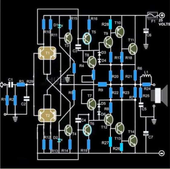
A quick glance at the given circuit diagram makes us conclude that the output configuration is not symmetrical, since the transistors T15 and T16 are both NPN types.
The input stage of the circuit begins or initiates with a symmetrical differential preamplifier stage consisting of the transistors T1, T2 and T3, T4.
T5 and T6 are positioned as the current sources which are further extended as the driver stage consisting of the transistors T7 and T8.
However a closer inspection tells us that of course the wiring is symmetrical, having the transistors T11, T13, T15 at the upper section acting like special booster transistor package.
Similarly the lower section also employs identical super booster stage consisting of the transistors T12, T14 and T16.
The above two sections are perfectly complementary to each other, with reference to the diagram which indicates their emitters being terminated to a common point through the resistors R25 to R27 and via R28 to R30, this effectively that the wiring is exclusively symmetrical by nature.
The output stage is able to produce a massive 200,000 times amplification factor with comparatively very low quiescent current drain.
The quiescent can be set by the adjusting the preset P1.
Due to a non critical nature of the circuit, the entire project can be easily built over a general purpose PCB, however the layout of the components or rather the placement and the ratio of the distance of the components must be kept as identical as possible to the layout of the circuit diagram.
Though a common heatsink may be used for the entire set of the output devices, I personally used separate individual heatsinks for each of the transistors.
This saved me from the headache of using the cumbersome and low efficient mica isolation kit between the transistors.
The inductor is kept for improving the dynamic nature of the circuit. It is built by winding 20 turns of super enameled copper wire over the 1 Ohms resistor itself.
The wire is selected to be close to 1mm in thickness.
Though not absolutely necessary, for better thermal stability the transistors T9 and T11 and also T10 and T12 should be glued together, preferably by attaching the respective pairs face to face.
The quiescent current should be ideally set to 50 mA through the following initial procedure:
How to Set Quiescent Current
1) Remove the speakers, and short the input terminals (across R1),
2) Connect a DMM set at current range in series with the positive of the power supply to the circuit,
3) Next adjust the preset such that the meter reads an input of 50mA, that’s all, the amplifier’s quiescent current is set and now the connections may be restored for the normal operations of the system.
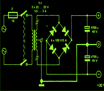
Power Supply Circuit
The power supply circuit is also shown along side and as can be seen there’s nothing special about it and may be built using the shown ordinary sets of components.
Parts List of 100 watt amplifier circuit (sh0wn below)
- R1 = 430 K,
- R2 = 47K,
- R3 = 330 Ohms,
- R4, R5 = 12 K ,
- R6, R7, R20, R21, R22, R23, R24 = 1 Ohm, 3 Watt, Wire Wound Type,
- R8, R17 = 68 Ohms,
- R9 = 100 K, R10, R11, R12, R13 = 5K6,
- R14, R15 = 12 K,
- R16, R19 = 100 Ohms,
- R25 = 10 Ohms / 2 Watts,
- P1 = 100 Ohms Preset, Linear,
- C1 = 1 µF / 25V,
- C2 = 1 n, CERAMIC,
- C3, C4 = 100PfC5 = 100 nF,
- C6, C7 = 1000 uF / 35 V,
- L1 = 20 turns of enameled 1mm copper wire over R24,
- D1, D2 = RED LED 5mm, All other diodes are = 1N4148,
- T1 = Matching BC546 pair,
- T2 = Matching BC556 pair,
- T3 = BC 557B,
- T4, T7, T8 = BC 547B,
- T5, T12 = BC 556B,
- T6, T9 = BC 546B,
- T10 = BD 140,
- T13 = BD 139,
- T11, T14 = 2N 3055
- General Purpose PCB,
- All the transistors T10, T13, T11 and T14 ae mounted on suitable heatsinks
The original design, (courtesy - elektor electronics)

The MOSFET version of the above design can be witnessed in the below given image:
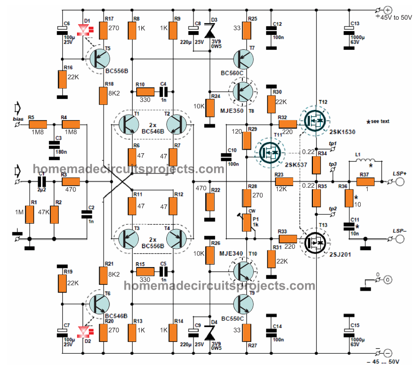
For the complete construction details, please refer to the following link:

Comments
I was Constructed a 30W+30W Cassette Deck very long ago, using N055 & P055 Transistor in Golden PCB (Gemini Radio, Chadni Chawk). I get the Circuit diagram from a book of Debashis Bandhopadhyay (ERC publication). Recently all Transistors are burnt out but, I want to repair the Amplifier. I have lost the book. I did not find the Transistor or Circuit Diagram in Gemini Radio. Please give me the circuit diagram of the amplifier of N055-P055. And suggest me where can I find the Transistor or it’s substitute.
Thanks in advance.
There are total 8 Nos of Transistor in a single side. 3 Nos BC548, 3 Nos SL100/sk100 and Two power transistor one N055 and one P055 (N055 and P055 are like 2N3055 package TO-3)
Please provide the approximate number of transistors and their sizes (package) used in your design, this will help me to identify a similar kind of circuit for you:
This amplifier is the modified version of the original 40+40w amplifier circuit by MD Hull a pioneer designer for Philips nv Netherlands. The circuit has very good bass and treble at very low volumes. I built this amplifier completely as per instructions ( book was published by Norman Brothers in India) in 1990 and is working perfectly to date. I had used only with modification of bd182 with 2n3055. The bass and treble control and the preamp were build and used as were given in book. The bass is far better than the now days used driver driven subwoofers. I had used 0-54v transformer 3A (guru make), dome tweeters*4 of Philips, mid range of 80w and woofers of 10 inch Bolton make with cross over. This whole audio system cost me around 8230rs in 1990's. But believe me even Bose or marantaz or sonos does not compete with it any way in any frequency levels. The bass and treble is very good.
n
By
Thank you for this interesting update!!
Whats the max input(audio) RMS voltage?
anything between 100mV and 500mV will be enough to get maximum output power
No, i mean how much is needed to achive the max power
you mean minimum, it's 100mV
how about these sanjeev…C2073 and A940.
i have question please it can work on 12 v dc ?
Tip 3055.
2N3773 IS better to use
I have made this apm on a protoboard…and for the love of God i cant make it work…the input just gose to the speaker with no amplification and the amp draws 2A, i have used the undmodified circut…i have used bc557c and bc447c insted of the b version, is that a problem?Suplly is +-25V
BC447 is not the problem unles it's faulty…the circuit is huge and the fault could anywhere in the design.
the quiescent current consumption of the circuit without load should be first set to 50mA
this is done by shorting R1/C1 junction of the amp to ground, speaker connections open, ammeter connected in series with the ground line, and P1 adjusted until the meter reads 50mA
i'll try it on a proper PCB, then we'll see if it works..
Hi,
could you upload the pcb layout o send it to me to
Thanks
Hi, can you tell me the brand model of this circuit please ? , thank you
Hi, I saw this circuit a long time ago, but didnt had the time to actually do it, my question , is the schematic good ? ( i read here that the 2nd photo has some drawing mistakes ) and whats the name/model of the Amplifier, i heard it's crescendo. I have a couple of 2n3055 made in 88" ( i think they are better then the new ones ) also , its the 2n3772 " better " or at least can be used instead of the 2n3055 in this circuit ?, Thank you, sir !
Hi Bruno, The circuits are perfect! and will work no matter which one you build.
2n3772 is good, and can be used instead of 2N3055
Hi Gautam Kumar Goswami.
Sorry for the delay. PCB softcopy diagrams posted dude. Enjoy.
Lancy Felix.
Please send me the soft copy of the PCB layout to my email: geotek_co@yahoo.com
good evening beautiful project . it would be possible to have the technical data of the amplifier ? is it possible to have the PCB soft at chri3399beltrami@gmail.com?
thanks christian
thanks, you can refer t the following pdf for more details:
raylectronics.nl/pdfs/Crescendo_Millennium_en.pdf
Hello sir. I am constructing this amplifier. Please send me the pcb layout at telangrajiv@gmail.com
Rajiv
Hi Lancy Felix, my name is Gautam Kumar Goswami & I am a Hi Fi Buff. I want to build this 2N 3055 based 100W power amp. Kindly send the PCB diagram soft copies to my email id : geotek_co@yahoo.com
Thanking you in advance,
G.K.Goswami
Dear Mr. Swagatam Majumdar, I want to build this amp & for this I need help from you. One is the PCB in soft. Can you please send it to my email id ? I also need a suitable preamp & tone control unit suitable to its specification. My email id is : geotek_co@yahoo.com
oh..sorry, it's not available with me at the moment…
Dear Mr. Majumdar, I requested for the output 2 x 2N3055 based 100W amplifier PCB in soft & its current upto dated circuitry. Please help. My email is : geotek_co@yahoo.com. Thanking you in advance,
Dear Gautam Kumar Goswami, you can find all the details in the following article:
http://www.eeweb.com/project/circuit_projects/300-watt-mosfet-real-hi-fi-power-amplifier
Please send me the PCB diagram. My email is : geotek_co@yahoo.com
Is this a 2.1 amplifier? Or just mono?
It's a mono amp…you'll need of these to get a stereo output
I am an audio buff. Can you please send me the soft copy of its pcb to geotek_co@yahoo.com ? Please help.
Please Swagatam Sir, Kindly upload corrected diagram for error free and last long daily use of this project.
Good morning Abinash, sorry that won't be possible because it was built and used by me a long time ago, and was later dismantled for some other purpose
Good Evening Swagatam Sir,
If possible, can you please upload a video in youtube of 2N3055 amplifier you have already made in the year 2000. So we can able to hear sound quality of this Class A amplifier.
Abinash, commenting in the my website is the best way to get in touch with me without fail….for image presentation you can submit it to:
admin @ http://www.homemade-circuits.com
Thank you Swagatam Sir, for your quick reply. Please give your email id for share some valuable information with picture about this project. I will expect support like that from you in future also.
Hi Abinash, who said the diagrams were not correct?…both the diagrams are perfect, however the last one has been tested by me…so you can try that.
Hi Khushin Makim, please send me the sof copy of 100 2N3055 PCB. My email id : geotek_co@yahoo.com
Thanking you,
Gautam Kumar Goswami
please send me the above pcb diagram at anwar621@gmail.com
Hi thanks for the info,actually my aim is to build a HI-FI 5.1 home theater system (100 watts in each channel if possible) with tweeter + mid range speakers in 4 of the channels and the rest would be center and sub.So pls advise me what circuit would be the best for this….thanks in advance.
You can try the following simpler design, it also has been tested by me:
https://www.homemade-circuits.com/2012/04/how-to-make-simplest-100-watt-mosfet.html
Hi, I would like to know if this circuit is used for creating 5.1 channel amp then how many transformer is needed……in other words how do u power this amp
the amp is powered from the shown power supply design and the signal input is acquired from any music system headphone out
Hi, you could use the above circuit along with the following one for getting a proper 5.1 implementation
https://www.homemade-circuits.com/2012/08/exploring-ic-tda-7560-4-x-45w-quad.html
good day can i use a 18-0-18v, 6amp transformer for this amplifier, thanks
yes will do…
Can I build this without any printed circuit board? Or is printed circuitry required?
It is suggested to stick to diagram layout yet two pairs of transistors are suggested to be glued together. They are in widely different parts of the diagram. How to do this? 'Fold' the circuitry up? Or have long leads to the transistors, putting them above the rest of the circuitry.
This will be a first project ever for me.
🙂
OK..the transistor glueing instructions is relevant to the last diagram…I hope you won't have to fold the PCB now:)
yes you can do it, because I myself built it on a dot matrix PCB and succeeded in the first attempt…refer to the diagram that's given in the bottom of the article, I think the transistor glueing info may not be correct so don't do it, I'll check and update the correct data soon.
okey sir. thanks a lot. ill notify you for an update.
sorry sir but im new to potentiometers. should I use the center terminal and one outer terminal?
the center lead is the important one, the other one could be any one of the outer two leads.
and lastly sir, this is the schematic diagram which my classmates used. is this the same?
http://www.brighthubengineering.com/diy-electronics-devices/94189-make-a-100-watt-transistor-amplifier-circuit/
yes it's the same circuit
we are also using 100ohm preset trimmer with the middle pin connected to one of the front pins.
that's fine…
Good day sir. We already made the amp but without the inductor first because we didnt have the chance to buy today. We have a little problem. the sound was too low. like there was no amplification. but we used a mono jack to connect to our cellphones. maybe it was the problem. or is it something else? we are so close to finishing this project. is there something we can do? we will try to use a 3 pin stereo jack tomorow and short the left and right. will it be okay? thank you sir.
presets do not have polarities, just use the center lead and any of the outer leads of the preset for the connections….. anyway round…the other outer lead can be left open or unconnected
it should be very loud, the vibration on the speaker cone should be very high and visible to eyes…something may be not correctly done or the components may be faulty
check and set quiescent current as explained in the article.
and can the V+ and ground terminals of the P1 interchangeable?
yes sir. i can hear a buzzing sound but not that loud. and i can also hear a little hiss when i turn the amp on. but the sound is not that loud.
by the way make sure to set the quiescent current with the help of the given preset in the amp….otherwise the circuit will waste a lot of power unnecessarily.
mono or stereo input is not the problem…the problem is surely in the amplifier circuit itself….
Good day Evo,
do not connect any music at the input just touch it with your finger, it must produce a very loud buzz in the speaker, and a small hisss when the finger touch is removed…..if this is not happening surely there's something terribly wrong with your circuit assembly.
I built the second design in the year 2000 when I was quite new to electronics, yet I succeeded to get the best response from it at the first attempt….i had used a general purpose board…not even a PCB
Okay sir. Thanks a lot. I'll notify you as soon as the amp is done.
i think the line is an excess sir. thank you very for your help.
yes that's right, wind the copper wire directly over the resistor and then solder the leads (resistor and the coil) together across the given PCB holes.
do you mean i'll put the inductor on top of the resistor? or wrap the resistor? sorry sir coz im a little confused. then connect their legs in parallel. thank you sir. I still have to wait until monday to resume making the amp. thank you very much sir for your non stop help.
Yes it will do…
for the inductor simply wind any moderately thick magnet wire over the resistor itself….wind 20 turns.
Good day sir. I used 4 capacitors for the parallel connection with 560nF. their result will be closer to the sum of 3 capacitors of 820nF. I havent tried it yet coz I have a difficulty having the result of 4-6uH for the inductor and my potentiometer broke. thank you for your help sir.
Evo, the new version is also correct except C7 which needs to be reversed and R12 ground side short, except these two drawing mistakes all seems right in the diagram.
connecting 3 in parallel will have other benefits but you can also try a 3.3uF instead it would do any harm.
One last thing sir, in the original design, there are C3, C4 and C5 connected in parallel with 820nF each. We have a difficulty in resources here so I cant find an 820nF. But when the three are added, they will have a sum of 2.46uF. The nearest capacitance I can buy is 3.3uF. And I have no choice but to change the three capacitors with one 3.3uF. Im just not sure if this is still okay. I apologize sir but I'm new to this. You've been a great help.
thank you very much for your help sir.
I would also like to inform you that my classmates had a problem with the new version of the design. the LED on the upper part wont turn on, T13 explodes and C7 is connected on the wrong terminal. The first time they turned it on, C7 exploded. I think its because the positive terminal of the capacitor is connected to the negative of the power supply.
That's why I decided to make the original version. I'll also update as soon as I finish this project. Thank you very much sir Swagatam.
Good day evo, there won't be any technical problem if the voltage is decreased, the wattage of the amp will decrease proportionately…. that's all .
Good day sir. I already decided to make the original version and currently building it. My only concern is that my transformer is only around 21-0-21 and after the rectification it goes up to 28-0-28. It would be good to the new amp design but in the original it indicates around 30 to 35v input. Im a little under voltage. Will this be a problem?
the extension from R12 ground towards left is a drawing mistake, rest everything is correct in the first diagram.
this part sir, at the picture. the horizontal line.
http://www.4shared.com/photo/D7dy-2CJba/amplifier-100-watts.html
thank you for the response.
Evo, please go with the following diagram, it's the original one and is more correct:
4.bp.blogspot.com/-6H3usY45JAM/UThb0mHH85I/AAAAAAAADdU/wNpmxml3ph8/s1600/100+watt+amplifier+circuit.jpg
good day sir. I am currently making this circuit. I just have a question. At the bottom left, is there really a connection under R12? I just notice that there was an excessive line going to the left and it is not like the one on the top left. I am just confused because if they are really connected, then the non-connected lines between R14 and R19 are useless. Can you please clarify sir? I will wait for your response to be able to continue the build. Thank you.
good day Evo, i can't see any extra line anywhere, R12 and R11 rails seem exactly symmetrical…did you click the image to enlarge?? please click it to enlarge.
R14 and R19 are wide apart, they have no link at all…I hope there's some confusion in reading the diagram from your side…enlarging it will clarify it
Good day sir. Could you please send me a copy of the PCB layout. Thank you very much.
evokhyn@gmail.com
power supply outputs will be +25 0 -25V dual supply but after rectification it could well become +32 0 -32v
And I also noticed the power supply circuit. Is the output going to be 25V/5A? Coz I can see a 30V on the bottom left. thank you sir.
Hi Swagatam sir
please send me the above pcb diagrams.
my email id: bhudha@gmail.com
can we use tip or mje 3055 in place of 2n 3055 and which will be better
will require too many modifications,…
Is it possible to convert a existing 2n3055 based amplifier into a mosfet one.
can we use MIC 6A4 diode in power supply.
Hi from Athens, could you please send me the PCB layout for this amplifier.
My email is panzac5@gmail.com
Thank you very much
sorry, PCB layout is not available…….
sir i need regulator power supply for luxion 1watt led i want to connect 8 led's input voltage 24v
thank you sir
use the following circuit
https://www.homemade-circuits.com/2013/06/universal-high-watt-led-current-limiter.html
I adjusted the P1 with an multimeter in series with (+) to the power supply, but no matter how much I djusted the 100Ohms preset, it only showed around 3-5mA
there's something not correct in your circuit, check all the connections many times you should be able to locate the fault…I built this circuit some 10 years ago and succeeded at the first attempt.
Hi again
I have built the amplifier, and i am getting an amplified signal out of the speaker, but it is very quiet, and a bit distorted. I tested the voltage over all the tranistors, and its at approximately 35 volts, except the T7+T8 – they are only showing between 0,1 – 1V. What could I be doing wrong?
No, there's definitely something hugely wrong with your connections or the parts.
Once built and set the output should provide a large amplification, even without any input music you should be able to hear a big Hiss on the speaker.
did you adjust the quiescent current as suggested in the article??
hi Lancy Felix
is it possible for you to send me a pcb layout for this amplifier?
my email address is ttararo@gmail.com
much appreciated.
posted dude.
Hi guys, could you please send me the PCB layout for this "Crescendo" amplifier. My email is ttararo@gmail.com.
THank you in advance..
So, ff I measure between;
+ & 0 = 25V
– & 0 = 25V
+ & – = 50V
Correct? 🙂
correct!
Okay, thanks again 🙂
This looks like a very nice amplifier, thanks for the detailed schematic and items list! I have just ordered the components and I'm excited to get started!
I have one questin though – I can't seem to figure out the recommended power suppy voltage/current. I'm confused with the shchematic sayin "Tr1, 2 x 25" Do I need a dual transformer, or?
If I only need one, will 30 Volts at 5 Ampere be suficient? Can less do it?
Im planning on winding my own transformer, so no need for "standard values" 🙂
(+) ans (-) supply lines will also need to be joined as common rails for both the units….
separate power supplies won't be required, you can use the same supply, just by making the grounds common…
Thank you very much. If I want to make 2 of these amplifiers, one for each channel, can i just make two identical amps and ground them to the same "0" on the transformer (offcourse with twice the current), or do I need 2 seperate center-tapped windings with their own respective "ground/0"
Thank you!
The transformer needs to be a center tap transformer, that is with two sets of winding on the secondary, rated as 24-0-24V at 2amps or more.
you can use a transformer rated at 30-0-30V/2amps also.
how can i contact you for a personal matter immediatly pleaseeeeeeeeeeee
in our city there was a young man. he makes subwoofers in home and sell them. but i dont have money to buy that. he has many types of subwoofers. like 5.1 , 2.1 , 7.1. now he is not here. but i want to make one. quality bass sound subwoofer circuit diagram. thats what i need. if you have that send me. i will give my email. thankz
…and please do not include external links, i'll just keep deleting them.
I have seen your link, yes you can use it with the above circuit
sorry, presently the pcb design is not there with me…
ow do you have above amplifire pcb diagrame?
presently i do not have it, i'll try to post in soon and let you know.
do you have is there any subwoofer circuit schematic. if you have please send me. Because i want a good bass. thats what i like
I'll try to include it soon in this blog and give you the link….
what is the correct swg for the L1 coil
20SWG
is there a good quality bass in this amplifire.
you can get god bass only after including a bass/treble circuit at the above amplifier input
no no I mean the sound. can i get a good bass sound from this
No, it does not include bass control, you will have to add it externally
please tell me
i00.i.aliimg.com/photo/v0/309836240/TIP3055_Power_NPN_Transistors_ST.jpg
img.bhs4.com/fa/d/fadf150f65b8acbacfb586f7ab802d0a80dced83_large.jpg
checkout this links and tell me the witch transistor is good for this circuit. please some one send me the PCB soft copy. upload that and give me the download link.
yes you can use them, be sure to add large finned heatsinks to them
i00.i.aliimg.com/photo/v0/309836240/TIP3055_Power_NPN_Transistors_ST.jpg
then can I use this transister
as mentioned in my previous comment, both the transistors are good and rated almost equally, it depends which one you prefer as per your convenience.
The value of L1 has been updated in the parts list.
please some one send me the PCB soft copy. my email- manujamicro1@gmail.com
can you send PCB soft copy to my mail:- manujamicro1@gmail.com
can you post a completed circuit with all parts
there are 2 types of 3055 transistor. first one is 2N3055 and other one is TIP3055. TIP3055 is a big transistor. 2N3055 is like a normal transistor. which one is good for this amplifier. I cant understand the L1 . How can i make it in home. I'm stuck in this plese reply me soon.
Both the transistor types are almost identical with their specifications, only the package is different.
You can use any of these as per your convenience….I have updated L1 data in the parts list.
Would it be okay if i use all the smd component instead of through hole component ,can my circuit behave diffrently under smd components ????
Please answer ……
yes you can use SMD, the circuit will work perfectly with them too, no issues.
That's great support Lancy, Thanks very much.
Don't use passive filters, use active filters as it will enhance the effects rather than deteriorating.
You can use the circuit IC2A/B section of the circuit shown in this link, use it in between your amp and music input:
https://www.homemade-circuits.com/2012/01/how-to-make-your-own-active.html
what is the different between digital ground and analog ground and how to joint these two grounds
it's a big explanation, cannot provide it here….these grounds are intended for providing discrete paths for analogue and digital signals, they should not be joined.
sir i want buffercircuit & bass boost circuit using op amp
sir hoe to cut below 80HZ in low pass filter circuit
By carefully adjusting the 22k presets.
Hi Kanagaraj, You can make this circuit:
https://www.homemade-circuits.com/2012/02/how-to-build-automatic-6-volt-12-volt.html
replace the feedback 1K resistor with 100k pot and remove the series 1N4148 diode.
sir i want one automatic battery charging circuit (12v) i want that circuit automatically sence low battery and start charging and cut the charging when the battery is full
sir hoe to increase left right bass depth without using tone controles (only using pre amplifier) if you have any circuit like that give me
You can replace the preamplifier with this circuit, it will work as both preamp and low pass filter:
https://www.homemade-circuits.com/2013/06/make-this-low-pass-filter-circuit-for.html
do you have any sub woofer pre amplifier circuit for this power amp if you have mean's wiil you please send me (kanagarajbe114@gmail.com)
I am sorry kanagaraj, I do not have any such circuit presently in my blog, I will try to update it if possible soon.
Thank you sir,and i want single supply transistor power amplifier circuit I have o-24 transformer 5amps
You can use the following circuit, just add a low pass filter at the input of the amp:
https://www.homemade-circuits.com/2012/04/how-to-make-simplest-100-watt-mosfet.html
Thanks for the help Lancy, keep it up mate:)
Sir,
I want to made this audio amplifier circuit. But in the amplifier circuit you show the 25V supply and in power supply circuit there is 30V.
What is co-relation between them. secondly, I want to known the rating of center tap transformer you have used.
Sudesh
After rectification the voltage may rise upto 30V, but it won't be a problem because the amplifier can handle upto 40V