In this post I have explained the basic construction of an ozone generator apparatus for disinfecting a closed premise from dangerous viruses such as coronavirus. Ozone is a tested and an officially recommended method of eliminating viruses and pathogens on outside surfaces.

Viruses Cannot be Killed with Medicines
The fact that makes a typical influenza virus or SARS a menace worldwide is that it cannot be killed with antibiotics, or any form of medicine. This is because viruses use the host's cells to replicate, which makes it almost impossible for the drug to distinguish the host cell from the virus. Due to this reason it becomes really hard for the medicine to target the virus without interfering with the host cell.
Also, drugs are unable to "kill" viruses simply because viruses are not living organisms, rather are complex bio-molecules, which stay inactive outside a living cell, and become active only once they enter a living cell.
The only way these may be eliminated is by natural means, such as by having a strong immune system, having plenty of rest, lots of fluid intake, and a pollution free resting place, possibly enhanced with oxygen supply.
What is Novel Coronavirus
The pandemic novel coronavirus, first detected in China (year 2019) is a type of virus that has proven to be even more resilient and dangerous than its earlier cousin, the SARS virus.
The World Health Organization was quick to declare the illness as a Public Health Emergency of International Concern. The disease caused by this new virus was named as COVID-19 (coronavirus disease -2019), and the virus was named as SARS-CoV-2 (severe acute respiratory syndrome coronavirus 2).
Novel Coronavirus Structure
As shown in the figure below, the SARS-CoV-2 molecules are roundish in shape and consist of proteins called spikes poking out from the body surface.
These spikes are used for hooking onto human cells, then undergo a structural transformation.
The process allows the membrane of the virus to merge with the host cell membrane.
Next, the virus releases its genes into the host cell so that it can duplicate it self, producing more viruses.
A detailed analysis of the internal structure of SARS-CoV-2 is given in the following data.
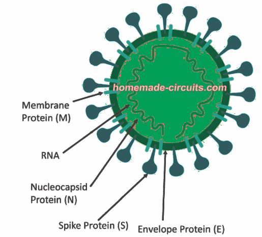
Nucleocapsid Protein (N): This section is attached with the RNA genome to constitute the nucleocapsid.
Spike Protein (S): It plays a vital role in binding with the host receptor cells to help easy entry into the host cell.
Envelope Protein (E): It works together with Membrane Protein to create the viral envelope.
Membrane Protein (M): It works as the main organizer of the CoV body, and also defines the structure of the viral envelope.
How Long can Novel Coronavirus Survive Outside a Living Cell?
It is still not confirmed for how long a SARS or a Coronavirus is able to survive over non-living surfaces. Researches have shown that an influenza virus is able to survive on an outside surface or outside a living cell for around 5 to 8 hours, under normal temperatures and environmental conditions. If an ordinary influenza virus can sustain for 5 hours then possibly the SARS-CoV-2 being more resilient should be able to sustain even longer.
Can Sunlight "Kill" Novel Coronavirus?
The bad news is, the SARS-CoV-2 will not die even under peak sunlight, unless the temperature is over 50 degrees Celsius.
Moreover, the UV rays from the sun is too weak to cause any harm to the coronavirus protein structure.
So sunlight cannot be considered as an effective source for killing coronavirus, but accumulated heat from sunlight, mainly in tropical countries might eventually eliminate these viruses, due to heated surfaces like roads, bridges, railings, vehicles etc.

Must Read: How to Make DIY Ultraviolet Generator Box, for Disinfecting Suspicious Objects
Can Ozone Gas "Kill" Novel Coronavirus SARS-CoV-2?
Yes, ozone gas can be effectively used for destroying coronavirus SARS-CoV-2, or any other virus.
The high oxidizing property of ozone gas can react with the external protein layer of novel coronavirus and rupture it, eventually causing an inactivation of the pathogen.
But, ozone gas can also damage human cells, especially the respiratory cells if the gas is inhaled, leading to cancer. Therefore, the procedure must be carried out without human presence in the chamber or the premise which is to be sanitized using ozone.
Ozone gas has the power to rupture the coronavirus protein layer, disintegrate it, and eventually destroy it.
What is Ozone
Ozone is an inorganic molecule with a chemical formula O3 hence is also called trioxygen. In nature ozone is usually produced through thunder lightening, due to corona discharge, and through UV rays.
Artificially, ozone can be manufactured through electric arcs or corona discharge set ups.
Both the above sets ups involve the generation of extremely high voltages which is able to break the air resistance and interact with the surrounding dry oxygen in the air.
Ozone from Corona Discharge
Corona discharge is emitted when a conductor open on one end, is subjected with an extremely high voltage in the order of many 10s of thousand of volts on its other end. This results in the conductor leaking the high voltage from its surface, which can be seen in the form of a faint purple light around the conductor in darkness. This light effect is called the corona discharge.
The interaction of this leaking high voltage with the oxygen molecules O2 causes the oxygen molecules to split into two oxygen atoms 2O, which reunite back with the neighboring oxygen molecules in triplets to form ozone O3 .
Ozone from Tesla Coil
A Tesla coil is a very popular high voltage generator circuit which is used for displaying bright purple flying electricity discharges from a coiled conductor terminal. Although it is fun project for creating ornamental lighting effect, the corona discharge ultimately results in the production of ozone which could be used for sterilizing a location from corona virus.
A simple Tesla coil circuit is shown below for experimental purpose, although the ozone generated from this set up will be too small.
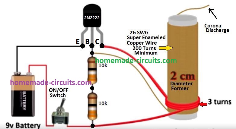
Once powered, the top open terminal of the 200 turn coil will begin emitting corona discharge, and this may also initiate the generation of ozone. To use this set up for killing coronavirus, operate the unit inside a locked premise with doors and windows closed. Make sure there are no living creatures inside the room. The Tesla coil circuit should be controlled with a timer so that it is automatically switched OFF after a a couple of hours. This timer must be accompanied with an exhaust fan so that once the ozone generation stops, the exhaust fan is switched ON to suck out the harmful ozone from the room. After about about 30 minutes from the elapsed time, it may be safe to enter the room, which now may be considered disinfected.
Ozone from High Voltage Arc
An electrical arc is formed when a high voltage source is brought near a neutral or grounded terminal. Due to the high voltage, the electrical charge is able to jump across the air gap to produce an electrical arc or spark.
This high voltage electricity breaks the air particles around the arc by the process of ionization which results in the generation of ozone.
In air, oxygen is in the form of dioxygen molecules O2. When a high voltage electrical arc comes in contact with O2, it cleaves the molecule into two to create two separate oxygen atoms 2O. These free 2O oxygen radicals disperse around and recombine with other dioxygen molecules to produce O3 which is ozone gas.
The reaction can be interpreted with the following chemical formula:
3O2 ➝ 2O3
A simple high volatge arc generator can be built using a CDI ignition coil set up as shown below:
Using Automobile Ignition Coil for Generating Electrical Arc
For generating rapid and high concentration of ozone, the following high voltage arc generator can be used, which is built using a standard automobile ignition coil and a CDI circuit:
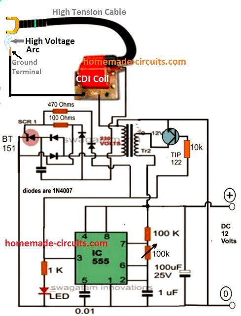
The set up looks simple, and just needs to be connected as per the given schematic for getting the proposed high voltage arcing and ozone generation.
You will require the following parts for the construction:
- 1/4 watt 5% Resistors 1k, 100k, 10k - 1 each
- 1/2 watt 5% resistors 470 ohm, 100 ohm - 1 each
- Potentiometer 100k - 1no
- Electrolytic capacitors 1uF/25V, 100uF/25 V - 1 each
- 0.01uF ceramic disc - 1no
- 1uF / 400V PPC associated with the SCR - 1no
- SCR - BT151 philips
- Diodes 1N4007 = 4nos
- Transistor TIP122 - 1no
- IC 555 - 1no
- Two wheeler Ignition coil unit - 1no
- Transformer 0-12V/1 amp/220V
- Mains AC to 12V DC adapter for powering the circuit
Adjusting the 100 k pot will allow the spark to be slower or faster, and also stronger or weaker.
The sparks generated from this circuit will generate high amounts ozone for disinfecting any standard room from coronavirus. However, make sure the gas is not inhaled by any living creature. Also, the voltage generated from this apparatus can be up to 30 kv, and therefore can kill a human within seconds, so please proceed with caution.
Again, use of a timer is recommended for automatically switching OFF the system, and switching an exhaust fan.
Conclusion
Ozone generators can generate ozone from surrounding atmosphere and are often applied as room disinfectants.
The antipathogenic reactions of ozone have already been confirmed since many decades. Its eradicating actions on bacteria, viruses, fungi, and in numerous types of protozoa, are the mains reasons why it's being increasingly employed for sanitizing municipal water supplies in towns globally.
Normally, viruses tend to be tiny, individual contaminants, made with crystals and macromolecules. As opposed to bacteria, these elements can multiply only inside the host cell. Ozone kills viruses by diffusing through their outer layers of protein into the central nucleic acid, causing instant destruction of the viral RNA. At increased levels, ozone ruins the capsid or exterior protein covering through oxidation.
The majority of analysis on ozone's virucidal benefits have focused on ozone's predisposition to bust apart lipid molecules at areas of multiple bond construction. This implies that, when the lipid package of the coronavirus is broken, it may become impossible for the DNA or RNA of the virus to survive any longer.
WARNING: All the concepts explained above have dangerous and life threatening consequences if not used correctly or with due precautions. The author cannot be held responsible for any damage to life, property, health, or whatsoever, in regard to the construction and usage of the above explained theories.


Comments
Thank you. I will study it.
hello Swagatam,
I have researched the topic of the rating of the primary of the TV EHT coil and I am unable to find the rating of the voltage of the primary of the TV EHT coil I have, nor of any other coils.
Do you know how to do this?
Even better, do you know of a source of TV EHT coils that have primary of 220V primary? or perhaps even 110V might work as well.
Thank you. I am very stuck here.
Hello Moshe,
I have never used an EHT coil in my experiments so far, therefore I have not idea regarding its pinout details.
Hello Swagatam,
I believe the 220v input voltage at the flyback may be higher than I need. i’d like to keep the input lower to have a lower voltage arc. So I plan on trying it also with 12V-0-12V transformer instead of stepping up to 220V. Can you tell me what values need to change in the circuit to make this work if I am using a 12V input voltage at the flyback? Which resistors and perhaps which capacitors might need to change? Or can I use everything as is?
Hello Moshe, a flyback transformer cannot be used in the above CDI circuit, since both the coils have different specs. I have never used a flyback transformer in my experiments so I do not seem to have sufficient information about its pinouts and functioning.
hello Swagatam,
earlier, you stated:
“You may have to check the primary supply rating of the TV EHT coil, if it is within 100 to 200 V then it can be probably replaced with the ignition coil in the above circuit.
I guess TV flyback transformers accept 110V AC at the primary side.”
Isn’t a TV EHT coil the same as a TV flyback transformer? I thought, if I get a ferrite core transformer (I can get either a 12V-12V with ferrite core or a 12V-220V with a ferrite core) and then use a TV flyback (which also uses a ferrite core) then this can work with this circuit? you said so earlier. Am I not understanding something?
Hello Moshe, yes if you can match everything correctly as specified then it might work.
Thank you Swagatam. You’ve been so kind and helpful. I really appreciate it.
I will try and report back in some time.
It’s my pleasure Moshe!
Thank you Swagatam. I really appreciate your help and your patience all these times.
I am glad to help Moshe!
Swagatam, yes. You are correct. However, the rotating magnets and hall sensors is just a model of the circuit. What I truly want are two solid state circuits.
In the simplest terms, Circuit A is 4 Hz and Circuit B is 6Hz, always in this ratio.
So if Circuit A is 400Hz, Circuit B will be 600Hz.
These will both trigger their own separate ignition coil circuits.
I can leave it at that, really. I’d like the frequency of Circuit A and Circuit B to be adjustable. I can manually adjust them to be the ratio I said about (4:6) but I do want them to be able to go high into KHz range.
There is also one complicated part.
the complicated part is that Circuit A and Circuit B must never fire at the exact same time. That was the timing diagram I sent you. They must fire as far away from each other as possible.
If this is too complicated, then I will just be happy to begin with the simple version.
What do you suggest? Can you help me with the complicated part as well?
If not, do you have any circuits planned out that I can use?
Hi Moshe, The timing adjustment can be complicated for me to understand and solve accurately for you. However, the two circuits A and B could be built using IC 555 with IC 4017. The outputs from the two 4017 Ics could be appropriately selected for getting the 4:6 ratio which can never fire at the same. However, if there’s a discrepancy in the frequency of the IC555 and if it deviates overtime, then we cannot guarantee the output sequence from the 4017 ICs….. at some point of time the two outputs can coincide and trigger the outputs simultaneously. To rectify this issue the frequencies of the 555 ICs must be highly accurate or crystal controlled.
hi Swagatam,
I am not sure I understand this, but will try to reply.
My answer is that every pulse of the IC 555 circuit will be one pulse of high voltage output from the flyback driver circuit. So 1:1.
My question to you is – how do we coordinate between the two IC 555 circuits so that they fire at the correct timing and do not fire at the same time? (as explained in my email)
Hi Moshe, As far as I have understood your question, you have two magnets on a pair of wheels which are supposed to trigger a couple of hall effect sensors at different times during their rotations. The signal from the hall effect sensor is supposed to trigger two 555 circuits to generate a pair of pulses for switching two separate ignition coil based circuits. This is all I can understand, any further than this can be difficult for me to understand.
hi Swagatam, I sent an email last week to your email on the contact page. Have you received it? Just checking in because maybe I sent it to the wrong email?
Hi Moshe, yes I saw it just now.
It can be solved by using two separate 555 IC monostable circuits for the two trigger inputs, however how would you want the output from the IC 555 circuits to be? Do you want them to be a simple one-shot high output or should the output be a multi-pulsed output?
hi Swagatam, I sent a reply to the email I had which is wordpress a….t….. http://www.homemade-circuits.com. is that the correct one? If not, please advise where I can send to you? thank you.
Hi Moshe, my email ID is given in my contact page.
hi Swagatam, Yes. I do need a small but potentially challenging addition to this circuit. I am running 2 circuits. They will be identical to the above circuits. However, they each have a different frequency and they must not strike ever at the same time. So this is the special part. The ratio between their frequencies is 4:6 – when Circuit A (eg 400Hz) is firing Circuit B (eg 600Hz) must not fire and when Circuit B is firing, Circuit A must not fire. In fact, they must be programmed to fire as far away from each other as possible. I have a schematic of how this is done with angles if you’re interested. I am not sure how to send that to you?
I also have a rotary circuit that I had built to perform this exact thing, but I’d rather do it solid state. However, the rotary circuit explains very well the concept of what I am looking to build in solid state.
Hi Moshe, I think this can be done using 4017 IC, with a 555 oscillator driving the 4017 IC. You can send the schematic to my email. If I can figure out the schematic then I will try to solve it for you.
You helped me customize the circuit for the HV ozone generator to kill covid using flyback coil.
https://www.homemade-circuits.com/wp-content/uploads/2022/02/high-voltage-generator-ozone-using-external-pulse.jpg
Now, I would like help to make something like an adjustable frequency 555 timer circuit to drive this HV flyback circuit. It is straightforward but there is a “twist” which I need help with. Can you help?
The high voltage generator with adjustable IC 555 is already given in the above article….you can build the same circuit. Please mention if you need any further modifications in that circuit.
Hi Swagatam. I hope this note finds you well. I would like your help in designing the “front ” part frequency generator. I wanted to write you on your page where you offer suggestions but the comments are closed. How can I reach you about the specific circuit I am trying to create?
Thank you Moshe, which circuit are you referring to? Is it the IC 555 oscillator circuit?
This is a great article thank you.
I am looking for a circuit which can take a pulsed DC signal and amplify that pulsed DC circuit to HV plasma arc. The outcome would be something similar to this Ozone generator, but not a coronal discharge, but rather, a High voltage (20 KV) plasma arc which is pulsing at the exact same frequency as the supplied circuit. Please note: I already have the circuit designed and working for the pulsed DC frequency and need to amplify it to the HV to create a plasma arc. thank you.
Thank you, and glad you liked it.
The last circuit probably matches your required specifications. The TIP122 accepts external pulses from the IC 555 circuit and triggers the SCR circuit to create high voltage arcs from the ignition coil.
Thank you Swagatam.
Very good.
So if the TIP122 accepts the pulses from the IC 555 timer circuit, then, I could remove the IC 555 timer circuit from the equation since I am providing an external pulsed DC signal. Correct?
Could you possibly sketch what the circuit would look like without the IC 555 timer and how and where I would connect the +ve and -ve from the external circuit I have?
the external circuit is 5-20V pulsed DC. I can keep it closer to 12V if necessary.
You are welcome Moshe! Yes you can remove the 555 stage and use only TIP122, transformer, SCR, ignition coil stages to create high voltage through external pulses. Here’s how the finalized design would look like:
Thank you so much. I will study it further and perhaps get back to you with further questions… if you don’t mind. 🙂
Sure, no problems at all.
Hi Swagatam.
As I have studied this customized circuit you shared with me closer, I have a few questions –
1) There is no 100K potentiometer in the customized circuit you drew me. If I’d like to control the speed and strength of the arc, is it possible to still do so in the customized circuit? If so, where would the 100K potentiometer go? (Would it just go attached to TR2 of the ignition coil in the diagram?)
2) Do you have a chart for input voltage for approximate output voltage for this circuit?
For eg:
1V input = 5KV output.
5V input = 15KV output.
12V input = 30KV output.
Something like that?
3) Is there a maximum frequency that this circuit setup can handle?
4) A) In this customized setup you made for me, is the capacitor shown in this customized circuit the 1uF / 400V PPC (it looks to be associated with the SCR)? or does this capacitor have another value?
5) I see +12V for positive terminal of 12V power supply (From mains AC to 12V DC adaptor) and I see +1V to 12V pulse as the positive terminal for the pulsed input I am supplying. I only see 1 ground. Is the 12V power supply and the pulsed circuit I am supplying for frequency sharing the same ground?
Sorry if these are dumb questions. I am a real beginner in electronics.
Thank you.
Moshe
Hi Moshe,
It can be difficult to provide precise adjustments for this circuit. You can add a 10K potentiometer across base/emitter of the transistor, but I am not very sure whether that will help to adjust the arc strength or not.
The strength of the arc is actually controlled by the 1uF/400V capacitor….higher values will generate stronger sparks and vice versa. So you can probably connect a range of capacitors from 0.22uF/400V to 1uF/400V and select them through a rotary switch to get a better control on the strength of the sparks.
The speed of the arc and the how much distance it can jump will depend on its strength, which is determined by the 1uF/400V capacitor and also the rating of the transformer, the 12V supply current, and the ignition coil.
The frequency of the arcing will depend on the input pulse frequency, which can be up to a maximum of 100 Hz.
The pulse voltage along with the potentiometer can be also to some extent used for adjusting the strength of the arcs.
Yes the ground line of the shown circuit should be common with the ground line of the input pulse source.
Thank you for your responses.
I understand.
I wanted to double check with you that you meant 100Hz as the maximum frequency?
did you perhaps means 100KHz? 100Hz is very low for my required frequency. The circuit I am supplying will have frequencies quite a bit higher.
I might be able to do 1000Hz, but 10,000Hz would be even better.
If that is in fact the correct maximum frequency (100Hz) is there a way to adjust the components of the circuit to allow for higher frequencies? thank you.
hello Swagatam,
In other area of comments, this gentleman said the following:
“Donald Livesay says January 31, 2022 at 3:12 am
Hello.
By the way the speed master has a spark duration of 225us which is 4464 Hz so it seems it can handle any feq up to that point set by 555”
So 4464Hz is enough for me. Do you think he may be right? In that case, I can build this customized version of the circuit and be happy with that result.
Also, I am working on this with a friend of mine. He asked the following question:
There are older type of high voltage coils in TVs that power cathode tubes. Can this be interchangeable for cdi? The type he knows about has a freight core.
Getting a ferrite core transformer shouldn’t be a problem.
thank you.
Hello Moshe,
Since iron core transformers are used, the maximum frequency cannot be beyond 100 Hz, or 200 Hz at the most.
In the above circuit the CDI ignition coil’s primary is rated at 100 to 200 V, which is supplied by the transformer TR2. If the ferrite transformer primary is also rated with the same level of voltage then it can be replaced here, otherwise the input supply from the transformer will need to be modified accordingly.
You may have to check the primary supply rating of the TV EHT coil, if it is within 100 to 200 V then it can be probably replaced with the ignition coil in the above circuit.
I guess TV flyback transformers accept 110V AC at the primary side.
Or alternatively, you can create your own primary section and operate it with an external 12V pulse. An example design can be see in this video:
youtube.com/watch?v=PBfQzXdQNsc
Yes, the 1V to 12V input pulse frequency should not exceed 100 Hz, because the transformer and the ignition coil are built using iron cores which are not designed to handle more than 100 Hz and might heat up if exceeded. For operating with kHz range frequencies you might have to employ ferrite core based transformers.
I have a ferrite core based design in this blog, but it looks too complex for any newcomer. Here’ is the link to that circuit:
https://www.homemade-circuits.com/universal-multi-spark-enhanced-cdi/
Nikto covid ešte neizoloval a už sa hocikde píše, ako vyzerá, z čoho sa skladá. Zaujímavé.
This is just the site I’ve been looking for. I have an Associates Degree in Electronics and use it as a hobby. I like to learn and make stuff. I have made a few things and will retire soon, so I’ll have more time to play with those silly electrons. What fun.
Thank you, I appreciate your interest…please keep up the good work. Cheers!
Hi, Can this circuit be modified or can you help me with a new one wherein I can fix the same inside the AC unit which will help in killing the virus.
Infact I saw one person who is manufacturing similar one (UV unit) which can be fixed inside the AC unit and think it does not require people to stay out of the room.
Hi, Ozone gas in any form is dangerous for humans, and it is strictly not recommended to be used at any place where humans or animals are present. If you put ozone in AC, the AC will throw it back in the premise and that can be too dangerous for the people present in that area.
Instead you can install UV lights inside the AC
Hi,
Is there any way to get rid of CORONA VIRUS like the above or UV light or any other way in which it can be kept inside the Hall, Rooms, etc which can function even with the presence of people.
Hi, there’s one related article in the following link which you can refer:
https://www.homemade-circuits.com/using-ultraviolet-chambers-for-disinfecting-humans-from-coronavirus/
Interesting but, dangerous
is this teory only? or anyone proof before?
Please provide scientific references regarding:
1. Ozone concentration and exposure time required to eliminate 99.99% of COVID-19 viral particles in a space
2. Method (s) used to confirm decontamination (culture swab, PCR, Chemical indicator, O3 concentration meter etc.)
Thank you!
Thank you for the very prompt reply!!
I am interested in providing a decontamination service using O3. Before undertaking the project, it needs peer-reviewed publications. I think there are “generic” papers, but not COVID-19 specific publications.
Tillman
Here’s one pdf file which contains all the details regarding the quantity and time required for inactivating various types of bacteria and viruses through ozone, hope this helps:
https://www.homemade-circuits.com/wp-content/uploads/2020/05/Ozoneusesandpotential.pdf
At this moment we don’t have any of those references or evidences with us, but surviving an ozone attack can be impossible for any virus or pathogen, that’s a proven fact.
Dear Rodolph
Can you give the circuit diagram. aloyalcin@hotmail.com
Thanks in advance…