We many times think that how we can make a SMPS circuit, and we feel that this is very complex. But that is not so because we can do this by following simple manual calculations step by step. We only need to know that SMPS design is always starting from the transformer. We cannot make flyback type design until we decide transformer turns, duty cycle, and inductance.
220V SMPS Designing Procedures
So here we will learn in a very clear step by step way how to design customized high current SMPS circuits. We will also make one example where we will convert 220V AC RMS input to 15V DC output at 80 amp, and we will use a 555 oscillator to run a MOSFET in flyback topology.
For quick Calculations you can try this SMPS Calculator
Step 1: Rectifying And Filtering The AC Input
We first look at the input. We have 220V AC RMS at the beginning. We must pass this through bridge rectifier and filter capacitor. When we do this, then we get almost 310V DC. So in our calculation we will take Vin = 310V DC as the actual input.
Step 2: Deciding The Output
Now we see what we need in the output. We want 15V DC and we want 80 amp current. That means the total power requirement is 15 × 80 = 1200 watts. So we must design the transformer that can safely transfer more than 1200 watts, otherwise the transformer will saturate and fail.
Step 3: Choosing The Switching Frequency
We must also decide the switching frequency. We know that if frequency is high then transformer size becomes small, but then switching loss will increase. Since we want a balance, so we choose 50 kHz frequency. So we will put Freq = 50 kHz in our calculation.
Step 4: Selecting The Core
We must select a proper ferrite core. Let us say we take an E core that is big and suitable. We suppose the effective cross sectional area Ae = 250 mm². We also suppose the magnetic path length Lcore = 80 mm. Relative permeability Mur we take as 2000. We also must decide the safe maximum flux density Bmax. We take Bmax = 250 mT or 0.25 T, so that the core will not saturate.
Step 5: Calculating Duty Cycle
We now calculate duty cycle. The formula is:
DutyCycle = (Vout + Vdiode) / (Vout + Vdiode + Vin).
Here we put Vout = 15V, Vdiode = 0.7V, and Vin = 310V.
So DutyCycle = (15 + 0.7) / (15 + 0.7 + 310) = 15.7 / 325.7 ≈ 0.048 or 4.8%.
So the duty cycle is very small, because Vin is very large compared to Vout.
Step 6: Calculating Primary Voltage
Now we calculate the effective primary voltage. The formula is:
Vprimary = Vin / (1 – DutyCycle).
So we put values: Vprimary = 310 / (1 – 0.048) = 310 / 0.952 ≈ 325.6V.
We see that the effective primary voltage is about 325.6V.
Step 7: Calculating Primary Turns
Now we calculate how many turns for primary. Formula is:
Np = Vprimary / (4 × Freq × Bmax × Ae).
We put Ae = 250 mm² = 250 × 10⁻⁶ m². Freq = 50 kHz = 50,000 Hz. Bmax = 0.25 T.
So denominator = 4 × 50,000 × 0.25 × 250 × 10⁻⁶ = 12.5.
Now Np = 325.6 / 12.5 ≈ 26 turns.
So we must keep around 26 turns for primary.
Step 8: Calculating Turns Ratio And Secondary Turns
We must now calculate turns ratio. Formula is:
TurnsRatio = Vprimary / (Vout + Vdiode).
So we put values: TurnsRatio = 325.6 / 15.7 ≈ 20.7.
Now we calculate secondary turns: Ns = Np / TurnsRatio = 26 / 20.7 ≈ 1.25 turns.
Since we cannot make fractional turns, then we take Ns = 1 turn. We must use one turn of very thick copper strip for secondary.
Step 9: Primary Inductance Calculation
Now we calculate Lp using this formula:
Lp = (Mu0 × Mur × Ae × Np²) / Lcore.
Mu0 = 4π × 10⁻⁷ = 1.256 × 10⁻⁶.
Now we put: Lp = (1.256 × 10⁻⁶ × 2000 × 250 × 10⁻⁶ × 26²) / (0.08).
= (1.256 × 10⁻⁶ × 2000 × 250 × 10⁻⁶ × 676) / 0.08.
≈ (0.000424) / 0.08 = 0.0053 H = 5300 mH.
So we see primary inductance is around 5.3 mH.
Step 10: Wire Selection
We must now select correct wires.
We see output current is 80 amp, so secondary winding must be very thick. It can be copper foil or multiple litz wires in parallel.
For 80A we need at least 80 mm² conductor cross section.
For primary we calculate input current:
P/Vin ≈ 1200 / 310 ≈ 3.9A.
So primary can be wound with around 2 mm² wire safely.
Step 11: Switching Device And Oscillator
Now we must select switching device. We can use a MOSFET or an IGBT that can handle high voltage.
We can select a 1200V 40A type MOSFET. The oscillator we make by using 555 timer in astable mode running at 50 kHz.
The gate of MOSFET must be driven through gate driver stage like IR2110 to ensure fast switching.
Step 12: Output Rectifier And Filter
We must also select correct rectifier. Since current is very high so we must use ultra fast Schottky diode or synchronous rectifier MOSFET on the secondary side.
We must also add large filter capacitor with ripple current rating more than 80A.
Step 13: Putting Everything Together
Now we can see the whole design clearly.
- Input is 220V AC which we rectify to 310V DC.
- Transformer has Np = 26 turns and Ns = 1 turn.
- Duty cycle is 4.8%.
- Output is 15V DC at 80A.
- Primary inductance is 5.3 mH.
- Oscillator is 555 running at 50 kHz.
- Switching is done by high voltage MOSFET with driver.
So this is the 220V SMPS full design step by step.
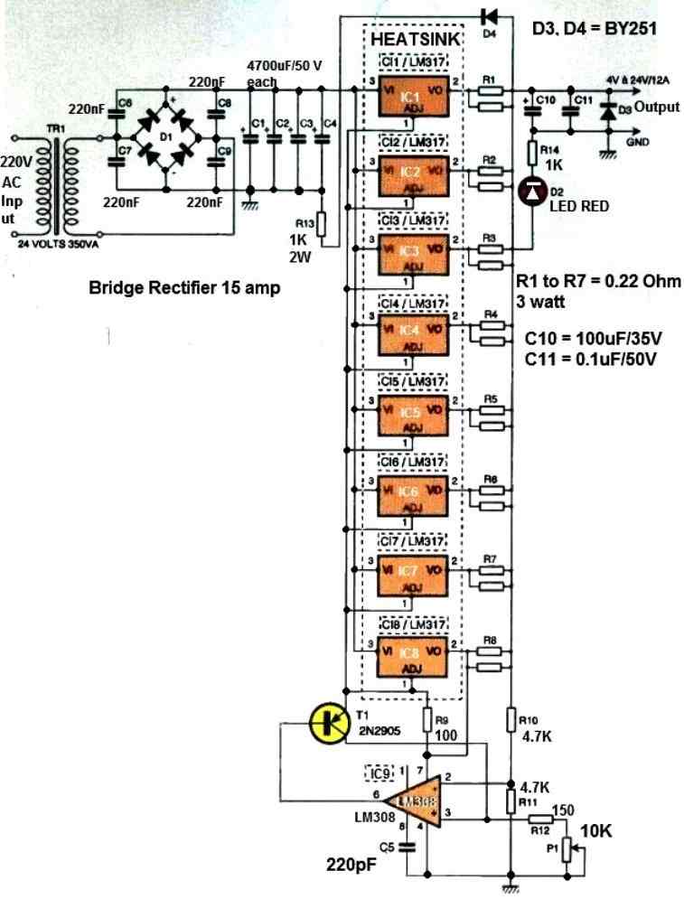
Example Circuit Diagram Using IC 555

Step 14: 555 Timer Oscillator — Working And PWM Generation
For Quick Calculations, you can use the following 555 astable Calculator
How The 555 Works In Astable Mode
We will now explain how 555 makes the square pulses, so you can see how the PWM is generated and fed to the MOSFET. The 555 has internal comparators and a flip flop, and it compares the capacitor voltage with 1/3 VCC and 2/3 VCC, and it changes the output and the discharge transistor accordingly.
When the capacitor voltage is below 1/3 VCC then the output goes high and the discharge transistor turns off so the capacitor can charge.
When the capacitor voltage rises to 2/3 VCC then the output goes low and the discharge transistor turns on so the capacitor discharges to ground.
This repeating charge and discharge of the timing capacitor creates a free running square wave at Pin 3 that we use as PWM. Texas Instruments
Standard Astable Equations And Timing
We will show the usual formulas so the reader learns how to choose RA, RB, C for the switching frequency. The standard astable timings are given by:
t_high = 0.693 × (R1 + R2) × C
t_low = 0.693 × R2 × C
So the frequency is:
f = 1.44/((R1 + 2R2) * C)
And the duty cycle is:
Duty Cycle = (R1 + R2) / (R1 + 2R2)
These formulas are the basic way we calculate the frequency and duty for a normal 555 astable.
Use them to get approximate values, and then tune on the real bench because capacitors and 555 thresholds have tolerances.
Why Standard Astable Cannot Give Very Small Duty (Less Than 50%) Without A Trick
We notice that in the standard formula Duty Cycle = (R1 + R2) / (R1 + 2R2) the duty can never go below 50% because R1 and R2 are always positive.
So if you want a very low duty then standard astable is not enough and we must do a small hardware trick with a diode to separate charge and discharge paths.
The diode makes the capacitor charge through one resistor only and discharge through the other resistor only, and this allows Duty to be much less than 50% if we choose resistor values right.
The Diode Trick For Duty < 50% (Practical For Flyback Low Duty)
We will explain the diode method because your flyback example needs a very small duty (around 4.8%).
In this method we place a signal diode in parallel with R2 so that during the charging stroke the current bypasses R2 and charges through R1 only, and during the discharge stroke the capacitor discharges through R2 only into pin 7. With the diode in place the timings change to:
t_high = 0.693 × R1 × C
t_low = 0.693 × R2 × C
So the total period T = 0.693 × (R1 + R2) × C and the frequency becomes:
f = 1.44/((R1 + R2) * C)
And the duty is now simple:
Duty = R1 / (R1 + R2)
This is the formula we use to get very low duty by making R1 much smaller than R2.
Example Calculation For 50 kHz And ~4.8% Duty Using Diode Method
Now we will show step by step how we choose R1, R2 C for the 50 kHz frequency used in the flyback example and we will target roughly the same duty that the transformer design wanted (4.8%).
We will use a practical small capacitor so the 555 can run stable at high frequency.
- We choose C = 1 nF (C = 1e-9 F) because we want a compact timing network for 50 kHz operation.
- We use the diode method formula for frequency:
R1 + R2 = 1.44 / (f * C)
So for f = 50 kHz:
R1 + R2 = 1.44 / (50e3 * 1e-9) = 1.44 / 5e-5 = 28,800 ohm
- Now we want Duty = R1 / (R1 + R2) ≈ 0.048 (4.8%). So:
R1 = Duty × (R1 + R2) = 0.048 × 28,800 ≈ 1,382.4 ohm
R2 = 28,800 − 1,382.4 ≈ 27,417.6 ohm
- We pick out nearest practical values that are available and safe. For example:
R1 = 1.2 kΩ (standard) and R2 = 27 kΩ (standard).
With these the actual numbers become R1 + R2 = 28.2 kΩ so f ≈ 1.44/(28.2e3 * 1e-9) ≈ 51.1 kHz and Duty ≈ 1.2 / 28.2 ≈ 4.26%.
This is close enough for our flyback primary duty. You can tune R1 a bit to move duty nearer to 4.8% if you want exact match.
So this is the simple step by step way to get a small duty using the 555 and one diode.
Wiring The 555 Pins In The Astable With Diode
We will explain how to wire the 555 in plain language so the reader can connect it on the breadboard:
We put R1 between VCC and Pin 7 (Discharge). We put R2 between Pin 7 and Pins 6 & 2 (Threshold and Trigger tied together). We put capacitor C from Pins 6 & 2 to ground.
We put a diode in parallel with R2 so that the capacitor charges by R1 only and discharges by R2 only. Pin 3 is the output square wave.
Pin 4 Reset must be tied to VCC so the 555 does not get accidentally held low. Pin 5 Control is normally decoupled to ground with 10 nF to keep thresholds stable.
Pin 1 is ground and Pin 8 is VCC. When you assemble this, then the output at Pin 3 will be the required PWM pulses. 555 pinouts
Driving The MOSFET Gate And Gate Driver Notes
We must not drive the MOSFET gate directly from the 555 for a high power flyback without proper gate drive. The 555 Pin 3 can source and sink tens of mA but the MOSFET gate of a big 1200 V MOSFET and the gate charge at 50 kHz will need fast current and proper level shifting. So the usual practice is:
We use Pin 3 to drive a gate driver like IR2110 or a dedicated MOSFET driver. The gate driver provides fast charge/discharge of the MOSFET gate and isolates the timing circuit from the high currents and voltages.
Also put a small gate resistor in series with the MOSFET gate to slow down dV/dt a bit and limit ringing. Use proper gate drive layout and decoupling capacitors.
Do not forget a pull down resistor on the MOSFET gate so the gate does not float when driver is off.
Remember that at high frequency then gate driver supply decoupling and ground layout are very important, so keep the 555 and its timing network physically separate from the MOSFET power loops, and then route the gate driver close to the MOSFET.
Practical Notes, Tuning And Safety
We must tune the R1 and R2 on the bench and then check the transformer magnetizing current and peak primary current.
The 555 based oscillator is simple and cheap but it has limitations: jitter, limited accuracy of duty at extreme low values, and it is not synchronous to any feedback loop unless you add a control arrangement.
For a real 1200 W flyback then you will likely need current limiting, startup protection, and an actual PWM controller if you want closed loop regulation. For simple experiments and learning then the 555 + diode method works well to show how PWM is generated and to drive a gate driver for the MOSFET.
Conclusion
So we understood that SMPS design can be done by following step by step manual calculation. We saw that first we rectify the input, then we decide the output, then we calculate duty cycle, then we find primary turns, secondary turns, inductance, and then we select wires and MOSFET.
So this way you can design your own flyback SMPS circuit for different voltages and current levels. The most important point is that we must always start with transformer design and flux density, otherwise the core will saturate and the circuit will fail.

Comments
Thanks Swagatam Sir. I really appreciate your response and help extended to me.
You are welcome Ravi kant, soon I would be updating the article with a professional half bridge driver design, because IC 555 is not a practical option, and may not work in a real life situation for a 1200 watt SMPS design…
can the calculation in the above design be appreciatable to every smps design
Yes, you can customize the calculations for any desired SMPS design..