In this article I have explained a very simple method of acquiring 220V DC from a 12V DC source. The idea utilizes inductor/oscillator based boost topology with the help of the IC 555.
Circuit Operation
Referring to the circuit diagram below, we see that the entire idea is based upon the versatile, evergreen IC 555.
Here it's configured in its standard astable multivibrator mode for generating the required pulses at a frequency determined by the resistors 4k7, 1k and the capacitor 680pF.
The duty cycle may be appropriately adjusted by experimenting the 1K resistor.
The output is received at pin#3 of the IC, which is fed to the gate of an N-channel mosfet.
When power is switched ON, the positive pulses emanating from pin#3 switch ON the mosfet into full conduction.
During the above periods the 12V high current potential is pulled to ground via the coil by the mosfet.
As we all know inductors always try to oppose instant changes in current polarity through it, therefore during the negative pulses when the mosfet remains switched OFF, forces the coil to dump the stored potential in it in the form of high voltage EMF pulse into the output.
This voltage may be equal to 220V DC and gives rise to the required potential at the shown outlet of the circuit.
The above straightforward operation is repeated continuously at the given frequency providing a sustained 220V DC at the output.
The BC547 and its base network is introduced for limiting the output voltage to the required degree.
For example if the required output is 220V, the 47K preset may be adjusted such that the220V mark never exceeds, irrespective of the coil back emf rate or the input voltage fluctuations.
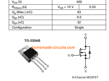
The mosfet can be any 400V, 50 amp type, for example a NTD4302 may be used.
The coil wire should be thick enough to hold up to 30 or more amps.
Circuit Diagram
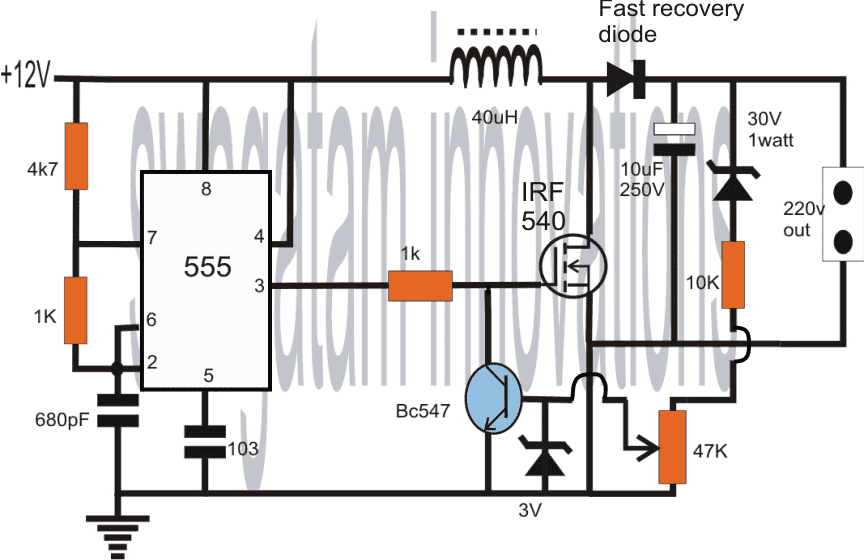
NOTE: THE MOSFET IS MISTAKENLY SHOWN AS IRF540, WHICH IS NOT APPROPRIATE FOR THIS APPLICATION, SO PLEASE REPLACE IT WITH AN IRF740 MOSFET.
WARNING: THIS CIRCUIT INVOLVES HIGH VOLTAGE, EXTREME CAUTION IS ADVISED WHILE HANDLING THIS CIRCUIT.
IC 555 Pinout Details

Mosfet IRF740 Pinout Details
How to Calculate the Inductor
Let's assume the maximum output current required is 5 Amps.
Then the total power output will be 220 * 5 = 1,100 Watts approximately.
So the maximum input current must be 1,100/12 = 92 Amps approximately.
The formula for calculating the Inductor is:
L = (Vin * D * (1 - D)) / (fs * ΔIL)
Where Vin = Input Voltage = 12 V
D = Duty cycle. This can be calculated as follows:
D ≈ 1 - (Vin(min) + Vds + Vf) / Vout
Where:
- D: Duty cycle
- Vin(min): Minimum input voltage
- Vds: Voltage drop across the MOSFET
- Vf: Voltage drop across the diode
- Vout: Output voltage
So, D ≈ 1 - (Vin(min) + Vds + Vf) / Vout
D ≈ 1 - [(12V + 0.5V + 0.7V)]/220V]
= 1 - 0.06 = 0.94
So, D = 0.94
fs = the 555 frequency at pin#3 or the MOSFET gate, let us assume the frequency to be around 300 kHz according to the R1, R2, C1 values for the IC 555 timing components.
ΔIL = Ripple current. Typically, the ripple current of 20-30% of the output current, so here it will be around 0.2 * 5 = 1 Amp
So, now let's plugin the above values in our Inductor formula:
L = (Vin * D * (1 - D)) / (fs * ΔIL)
= (12 * 0.94 * (1 - 0.94)) / (300000 * 1)
= 0.67 / 300000
= 0.0000022333 H or 2.2333 µH
So the value of the Inductor should be 2.2333 µH for getting 5 amp maximum output.


Comments
Hi,sorry for the inconvenient but is there a way to change the output from 220V to only 45V
Yes, you can build a custom design by using the following details:
https://www.homemade-circuits.com/ic-555-boost-converter-calculator/
what are the nmber of turns and size of wire
The number of turns will depend on the 40uH value, make the winding until the 40uH is achieved. The wire thickness will depend on the load current, for this project a 1mm copper should be quite enough for delivering 220V, 200 mA current output.
I can’t see the AC side of this circuit… looks like a boost converter can you explain how the ac signal is generated and captured? I’m really interested in what I’m missing here. Boost yes. Using the mosfet to switch short the inductor and capture the EMF. The BC547 regulates as described but maybe I’m misunderstanding something. Can you explain in detail? Thanks a lot Andrew
Sorry about the confusion, you are correct!
It is actually a 12V DC to 220V DC boost converter circuit.
I have now changed the article content and the title accordingly.
Hi
In order to work the mosfet have to be rated for Vdrain = Vout+Vf(diode). So IRF540 doesn’t fit for this application because his Vd max is 100V
Sorry, you are absolutely correct, please change the MOSFET to IRF840…
Agree
You are absolutely right, please upgrade the MOSFET to IRF840.
How is the above inductor wounded and using which wire
You can wind a 1mm thick super enameled copper wire over a ferrire rod. Create number of turns which produces 40 uH value
Excellent…
thank you
i want to use a 12v dc motor mechanically coupled at the shaft to another motor shaft of a 220v ac motor– the idea is to get 220v from the driving force of the 12vdc motor. am currently doing this with a hydro generator. again the idea is to have the 12v motor make the 220v ac motor supply power to feed itself with the proper invertors in line . can this work.
That is definitely possible, however the output power of the 220V motor will be just 70 or 80% of the 12V motor power.
How much time can I use from DC 12v 45 AH to AC 220v 65W?
Hi, I need to build a transformer to be used as a inverter. 12vdc input to 220vac output at 50 hertz.
The total load the transformer must be able to take is 4 KW. I would very much like to know the wire size in mm for the 220vac side, the thickness of the wire and the number of turns.
The same applies to the 12vdc side having a center tap.
If you have a schematic, using normal components for the low voltage side to create the 50 hertz, using Mosfets. I would need a pure sine wave and not a square wave.
I would really appreciate your help.
Hi, I do not have the details of the wire size for the transformer, it will need to be selected from a chart or a table maybe.
You can probably refer to the following article for any details:
https://www.homemade-circuits.com/how-to-make-transformers/
For the sine wave inveretr you can try the following concept:
Arduino Pure Sine Wave Inverter Circuit with Full Program Code
Thank you very much for your helpful circuits
fish shocker circui
Can you explain more.
Coil about 40 mikrohenry-how many turns on what(Ferrite ring,ferrite EE trafo or)Which diameter off wire?How many ampers in outside,outside power?
Can I run a1or 2 hp water pump ? Thank you very much.
No, you cannot run 2 hp load with this circuit
Then what I’ll do if I want to do this?I mean Is there any circuit or electonic devices you know to run 1hp load with DC? Thanks a lot….
you will need a 24V to 220V inverter 1 kva
Hello Swagatam!
Can this circuit be used to power the “Cell Phone Battery Charger Station in Villages “(www.www.homemade-circuits.com/installing-solar-universal-cell-phone/)
Hi Shigida, yes it can be used after proper adjustments
Swagatam,Thanks a lot.
would you mind telling me which part and how to adjust the ckt in order to get posibilly more watt out of it?
Shigida, you will have to manually experiment with trial and error, and find out which frequency produces the maximum voltage output, once this is fixed then you can replace the coil with a thicker wire coil for upgrading the current capacity of the coil.
If I convert a 12 or 15 or 50v to 230v can I connect this to home appliances if it is possible means please explain it in detail and if not means give the solution to implement the home appliances to it.
you can connect appliances which are SMPS based for exmple TV sets, LED lamps, amplifiers but not that require AC sinewave inputs like refrigerators, mixers, fans etc.
I can fool around with the RC timing parts of the ic to get the frequency but can you assist me with the coil, how man turns do you think I would need to get such high voltage.
you can try 100 turns initially, for more info you can refer to the following article
https://www.homemade-circuits.com/2015/10/calculating-inductor-value-in-smps.html
Can I adjust this to get about 40 to 60khz at about 400v ac?
If so do you have any idea how much turns I would need on the inductor.
yes that's possible by appropriately setting the coil dimension and the RC timing parts of the Ic
Sir, please, give me a..idea about dc to dc converter from 12volt to 36volt for my 30watt 36volt led chip.because,i have to drive this led light from 12volt battery…
Swapan, you can try the concept which is explained in the above article.
I need a circuit of 500 watt 12 volt DC to 15 volt DC converter
You make a mistake; put a high speed diode after switching.
If you work with SMPS, high speed diode always needed!
thanks, I have corrected it now!
this is an open source of Quantum telepotational electrical entanglimentals circuit resaunance pradox well done swagatam where advannce of mechanical stress will reverse as infinit power in the futures! your devotion is one of Quantum logic swagatam.
Hi Charm,
If the input is higher than 48V then the zener feedback stage will be required.
hi Swag will it be the same (no BJT+zenor) for 48v?
Endel, you can refer to the following post!
The first 3 circuits, all have a feedback control, but without an opto coupler. Opto coupler can be difficult to set, so no opto couplers are used.
https://www.homemade-circuits.com/sg3525-pure-sinewave-inverter-circuit/
I would like Mr. Swagatam engineer
to teach me how to put a feedback circuit
with photo coupler in an inverter output equal to 127vac
the feedback circuit will monitor this voltage of 127vac
and make sure that it never drops or changes in any way always form
127vac and never change. Mr. could be showing here
through an article
– CI USED = SG3525
– PHOTO USED = PC817
If the output voltage exceeds the zener value, the zener conducts and switches ON the BC547, which in turn switches OFF the mosfet ensuring that the output never exceeds the value of the zener voltage
Qual seria a função do DIODO ZENER , no circuito ?
Bonjour Monsieur.
Pour le transistor mosfet il faut celui qui peut supporter une tension de 220V ?
you are welcome Miracle.