In this post we will study how to connect solar panels in series and parallel and also learn how to calculate solar panels in series and parallel.
Before I have explained the connection details, it would be important for us to learn some of the important parameters and specifications related to solar panels.
Solar Panel Parameters
Following are some of the key parameters associated with solar panels worth studying.
Power output (P): It is the maximum power that the solar panel can generate. This specification is measured in watts (W).
Voltage (V): It is the potential difference generated between the positive and negative terminals of the solar panel. This specification is measured in volts (V).
Current (I): The flow of electrical charge through the solar panel is termed as the current (I). This specification measured in amperes (A).
Open circuit voltage (Voc): This is the maximum voltage that the solar panel can generate while it is not connected to any form of load across its positive and negative terminals.
Short circuit current (Isc): This is the maximum current that the solar panel can generate while its positive and negative terminals are shorted, or connected across each other.
Fill factor (FF): This is a measure of the efficiency of the solar panel. It is defined as the ratio of the maximum power that the solar panel can produce to the product of its open circuit voltage and short circuit current. FF = P / Voc x Isc
Temperature coefficient (TC): This is a quantity which indicates how the output voltage and current of the solar panel change depending on the changes in ambient temperature or the solar panel temperature.
Efficiency: This is a magnitude which indicates the percentage of solar energy that the solar panel can practically convert into electrical energy.
These parameters are important for selecting and designing solar panel systems, as well as for evaluating their performance.
How to Connect Solar Panels in Series and Parallel
Connecting solar panels in series and parallel are two common methods for increasing the voltage and current of a solar panel array.
When you connect solar panels in series, you connect the positive (+) terminal of one solar panel to the negative (-) terminal of another solar panel. The total voltage of the array will be the sum of the voltages of each solar panel, while the current will be the same as that of the solar panel having the lowest current specifications.
When you connect solar panels in parallel, you connect the positive (+) terminals of all the solar panels together and the negative (-) terminals together. The total voltage of the array will be the same as that of a single solar panel, while the current will be the sum of the currents of each solar panel.
The following are the formulas which can be used to calculate the total voltage and current for solar panels connected in series and parallel:
Formula for Calculating Solar panels connected in series:
Total Voltage = V1 + V2 + V3 + … + Vn, where V1, V2, V3, … Vn are the voltages of each solar panel.
Total Current = Imin, where Imin is the current of the solar panel with the lowest current.
Formula for Calculating Solar panels connected in parallel:
Total Voltage = V1 = V2 = V3 = … = Vn, where V1, V2, V3, … Vn are the voltages of each solar panel.
Total Current = I1 + I2 + I3 + … + In, where I1, I2, I3, … In are the currents of each solar panel.
Please note that when solar panels are connected in series, the total voltage of the array will increase, but the total current will remain the same as that of the lowest current solar panel. When solar panels are connected in parallel, the total current of the array will increase, but the total voltage will remain the same as that of a single solar panel.
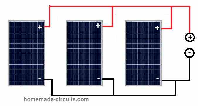
Connecting Solar Panels in Series (Practical Example)
For example, let's say you have three 100W solar panels with the following specifications:
Voltage (V): 18V Current (I): 5.56A
In order to connect these solar panels in series, you will have to connect the positive (+) terminal of the first solar panel to the negative (-) terminal of the second solar panel, and then connect the positive (+) terminal of the second solar panel to the negative (-) terminal of the third solar panel, as shown in the diagram below:
The total voltage of the array would be:
Vtotal = V1 + V2 + V3 = 18V + 18V + 18V = 54V
The total current of the array would be:
Itotal = Imin = 5.56A
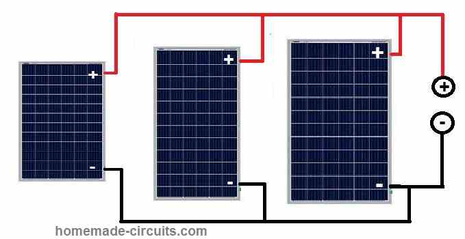
Connecting Solar Panels in Parallel (Practical Example)
In order to connect solar panels in parallel, you will have to connect the positive (+) terminals of all the solar panels together and the negative (-) terminals together. The total voltage of the solar panel array will be the same as that of a single solar panel, while the current will be the sum of the currents of each solar panel.
For example, let's say you have three 100W solar panels with the following specifications:
Voltage (V): 18V Current (I): 5.56A
In order to connect these solar panels in parallel, you will have to connect the positive (+) terminals of all three solar panels together and the negative (-) terminals of all three solar panels together, as shown in the diagram below:
The total voltage of the array would be:
Vtotal = V1 = V2 = V3 = 18V
The total current of the array would be:
Itotal = I1 + I2 + I3 = 5.56A + 5.56A + 5.56A = 16.68A
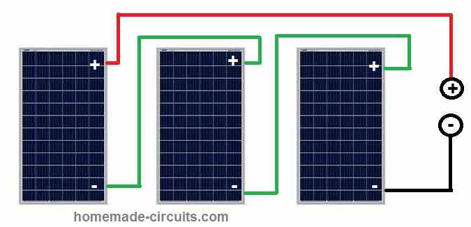
How to Connect Solar Panels in Series with Different Voltage and Current Specs:
Let's say you have three solar panels with the following specifications:
Solar Panel 1: 100W, 18V, 5.56A Solar Panel 2: 150W, 24V, 6.25A Solar Panel 3: 200W, 30V, 6.67A
If you want to connect the above solar panels in series, you will have to connect the positive (+) terminal of Solar Panel 1 to the negative (-) terminal of Solar Panel 2, and then connect the positive (+) terminal of Solar Panel 2 to the negative (-) terminal of Solar Panel 3, as shown in the diagram below:
The total voltage of the array would be:
Vtotal = V1 + V2 + V3 = 18V + 24V + 30V = 72V
The total current of the array would be:
Itotal = Imin = 5.56A (since Solar Panel 1 has the lowest current)
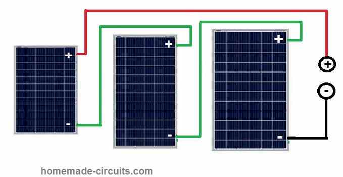
How to Connect Solar Panels in Parallel with Different Voltage and Current Specs:
Let's say you have three solar panels with different voltage and current specifications:
Solar Panel 1: 100W, 18V, 5.56A Solar Panel 2: 150W, 24V, 6.25A Solar Panel 3: 200W, 30V, 6.67A
If you want to connect the above solar panels with different specifications in parallel, you will have to connect the positive (+) terminals of all three solar panels together and the negative (-) terminals of all three solar panels together, as shown in the diagram below:
The total voltage of the array would be:
Vtotal = V1 = V2 = V3 = 18V (since Solar Panel 1 has the lowest voltage)
The total current of the array would be:
Itotal = I1 + I2 + I3 = 5.56A + 6.25A + 6.67A = 18.48A
It's important to note that when connecting solar panels with different specifications, the overall performance of the solar array may be limited by the lowest performing panel. Therefore, it is normally recommended to use solar panels having identical specifications, so that the overall performance of the system can be maximized.


Comments
in your help please if connect solar panels 550w (06) in series and another 550 w(06) in parallel then i connect them together in one solar inverter what could be the voltage output
You did not mention the voltage ratings of the panels?
How do I calculate efficiency of six solar panels connected in parallel?
Solar panel efficiency is normally around 20% only.
Awesome post! Connecting solar panels in series or parallel is an effective way to increase the voltage or current output of a solar panel system. Connecting panels in series involves connecting the positive terminal of one panel to the negative terminal of the next panel, which adds up the voltage of each panel. Connecting panels in parallel involves connecting the positive terminals together and the negative terminals together, which adds up the current output of each panel. It’s essential to consider the voltage and current requirements of the system and ensure that the panels are compatible before connecting them in series or parallel. Proper wiring and grounding are also crucial to ensure the safety and efficiency of the system.
But dissipation will be in the panel with lowest voltage when different panels connected in parallel. I guess this is not a healthy situation for the smallest?
That’s right, in that case it is better to use diodes across the positive lines of each solar panel to isolate them from each other.
Please sir can you do a diagram of this connection.
You just have to connect rectifier diodes in series with the positive line of each of the solar panels.