Interested to make your own power inverter with built in charger? A simple 400 watt inverter circuit with charger that can be very easily built and optimized has been provided in this article. Read the complete discussion through neat illustrations.
Introduction
A massive 400 watts power inverter with built in charger circuit has been thoroughly I have explained in this article through circuit schematics. A simple calculation to evaluate the transistor base resistors has also been discussed.
I have discussed the construction of a few good inverter circuits through some of my previous articles and am truly excited by the overwhelming response that I am receiving from the readers. Inspired by the popular demand I have designed yet another interesting, more powerful circuit of a power inverter with built in charger.
The present circuit though similar in operation, is more interesting and advanced due to the fact that it has got a built-in battery charger and that too fully automatic.
As the name suggests the proposed circuit will produce a massive 400 watts (50 Hz) of power output from a 24 volt truck battery, with an efficiency as high as 78%.
As it’s fully automatic, the unit may be permanently connected to the AC mains. As long as the input AC is available, the inverter battery is continuously charged so that it is always kept in a topped up, standby position.
As soon as the battery becomes fully charged an internal relay toggles automatically and shifts the battery into the inverter mode and the connected output load is instantly powered through the inverter.
The moment the battery voltage falls below the preset level, the relay toggles and shifts the battery into the charging mode, and the cycle repeats.
Without wasting anymore time let’s straightaway move into the construction procedure.
Parts List for the circuit diagram
You will require the following parts for the construction of the inverter circuit:
All resistors are ¼ watt, CFR 5%, unless otherwise stated.
- R1----R6 = To be calculated - Read at the end of the article
- R7 = 100K (50Hz), 82K (60Hz)
- R8 = 4K7,
- R9 = 10K,
- P1 = 10K,
- C1 = 1000µ/50V,
- C2 = 10µ/50V,
- C3 = 103, CERAMIC,
- C4, C5 = 47µ/50V,
- T1, 2, 5, 6 = BDY29,
- T3, 4 = TIP 127,
- T8 = BC547B
- D1-----D6 = 1N 5408,
- D7, D8 = 1N4007,
- RELAY = 24 VOLT, SPDT
- IC1 - N1, N2, N3, N4 = 4093,
- IC2 = 7812,
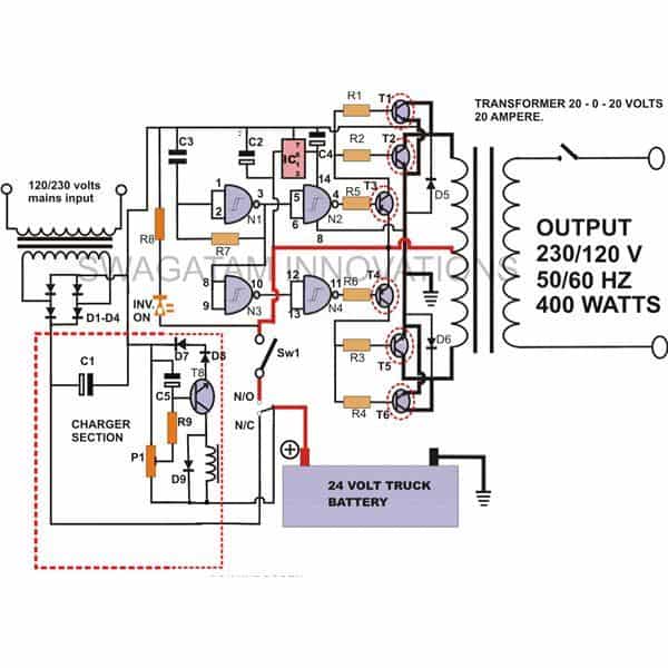
- INVERTER TRANSFORMER = 20 – 0 – 20 V, 20 AMPS. OUTPUT = 120V (60Hz) OR 230V (50Hz),
- CHARGING TRNASFORMER = 0 – 24V, 5 AMPS. INPUT = 120V (60Hz) OR 230V (50Hz) MAINS AC
Circuit Functioning
We already know that an inverter basically consists of an oscillator which drives the subsequent power transistors which in turn switches the secondary of a power transformer alternately from zero to the maximum supply voltage, thus producing a powerful stepped up AC at the primary output of the transformer.
In this circuit IC 4093 forms the main oscillating component. One of its gates N1 is configured as an oscillator, while the other three gates N2, N3, N4 are all connected as buffers.
The oscillating outputs from the buffers are fed to the base of the current amplifier transistors T3 and T4. These are internally configured as Darlington pairs and increase the current to a suitable level.
This current is used to drive the output stage made up of power transistors T1, 2, 5 and 6.
These transistors in response to its alternating base voltage are able to switch the entire supply power into the secondary winding of the transformer to generate an equivalent level of AC output.
The circuit also incorporates a separate automatic battery charger section.
How to Build?
The construction part of this project is pretty straightforward and may be completed through the following easy steps:
Begin the construction by fabricating the heat sinks. Cut two pieces of 12 by 5 inches of aluminum sheets, having a thickness of ½ cm each.
Bend them to form two compact “C” channels. Drill accurately a pair of TO-3 sized holes on each heat sink; fit the power transistors T3---T6 tightly over the heat sinks using screws, nuts and spring washers.
Now you may proceed for the construction of the circuit board with the help of the given circuit schematic. Insert all the components along with the relays, interconnect their leads and solder them together.
Keep transistors T1 and T2 little aloof from the other components so that you may find sufficient space to mount the TO-220 type of heat sinks over them.
Next go on to interconnect the base and emitter of the T3, 4, 5 and T6 to the appropriate points on the circuit board. Also connect the collector of these transistors to the transformer secondary winding using thick gauge copper wires (15 SWG) as per the shown circuit diagram.
Clamp and fix the whole assembly inside a well ventilated strong metallic cabinet. Make the fittings absolutely firm using nuts and bolts.
Finish the unit by fitting the external switches, mains cord, output sockets, battery terminals, fuse etc. over the cabinet.
This concludes the construction of this power inverter with built in charger unit.
How to Calculate Transistor Base Resistor for Inverters
The value of the base resistor for a particular transistor will largely depend on its collector load and the base voltage. The following expression provides a straightforward solution to calculate accurately the base resistor of a transistor.
R1= (Ub - 0.6)*Hfe / ILOAD
Here Ub = source voltage to R1,
Hfe = Forward current gain (for TIP 127 it’s more or less 1000, for BDY29 its around 12)
ILOAD = Current required to activate fully the collector load.
So, now calculating the base resistor of the various transistors involved in the present circuit becomes pretty easy. It is best done with the following points.
We start first by calculating the base resistors for the BDY29 transistors.
As per the formula, for this we will need to know ILOAD, which here happens to be the transformer secondary one half winding. Using a digital multimeter, measure the resistance of this portion of the transformer.
Next, with the help of Ohms law, find the current (I) that will pass through this winding (Here U = 24 volts).
R = U/I or I = U/R = 24/R
- Divide the answer with two, because the current of each half winding gets divided through the two BDY29s in parallel.
- As we know that the supply voltage received from the collector of TIP127 will be 24 volts, we get the base source voltage for BDY29 transistors.
- Using all the above data we can now very easily calculate the value of the base resistors for the transistors BDY29.
- Once you find the value of the base resistance of BDY29, it will obviously become the collector load for TIP 127 transistor.
- Next as above using Ohms law, find the current passing through the above resistor. Once you get it, you may go on to find the value of the base resistor for the TIP 127 transistor simply by using the formula presented at the beginning of the article.
- The above explained simple transistor calculation formula may be used to find the value of the base resistor of any transistor involved in any circuit
Designing a Simple Mosfet Based 400 Watt Inverter
Now let's study yet another design which is perhaps the easiest 400 watt sine wave equivalent inverter circuit. It works with lowest number of components and is able to produce optimum results. The circuit was requested by one of the active participants of this blog.
The circuit is not actually a sine wave in true sense, however it's the digital version and is almost as efficient as its sinusoidal counterpart.
How it Works
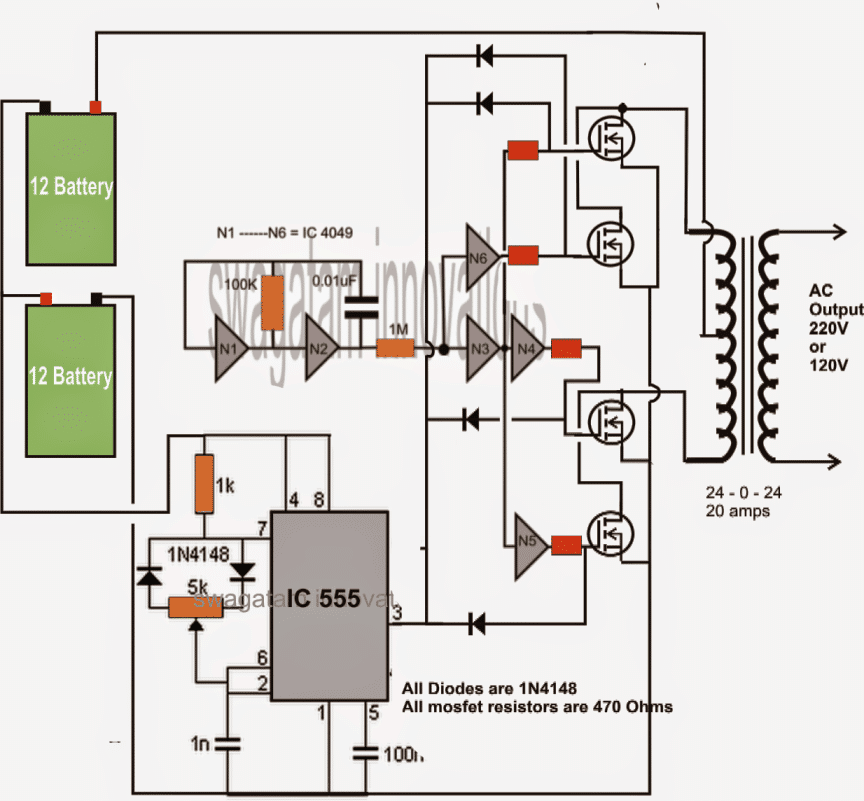
From the circuit diagram we are able to witness the many obvious stages of an inverter topology. The gates N1 and N2 form the oscillator stage and is responsible for generating the basic 50 or 60 Hz pulses, here it has been dimensioned for generating around 50 Hz output.
The gates are from the IC 4049 which consists of 6 NOT gates, two have been used in the oscillator stage while the remaining four are configured as buffers and inverters (for flipping the square wave pulses, N4, N5)
Until here, the stages behave as an ordinary square wave inverter, but the introduction of the IC 555 stage transforms the entire configuration into a digitally controlled sine wave inverter circuit.
The IC 555 section has been wired up as an astable MV, the 100K pot is used for optimizing the PWM effect from pin#3 of the IC.
The negative going pulses from the IC 555 are only utilized here for trimming the square wave pulses at the gates of the respective MOSFETs, via the corresponding diodes.
The MOSFETs used may be any type able to handle 50V at 30 amps.
The 24 batteries need to be made out of two 12V 40 AH batteries in series. The supply to the ICs must be provided from any of the batteries, because the ICs will get damaged at 24Volts.
The 100K pot should be adjusted using an RMS meter for making the RMS value at the output as close as possible to an original sine wave signal at the relevant voltage.
The circuit has been exclusively developed and designed by me.
Feedback from Mr. Rudi regarding the waveform issue obtained from the above 400 watt inverter circuit
hi sir,
i need your help sir. i just finished this circuit. but the result is not as what i expected, please refer to my pictures below.
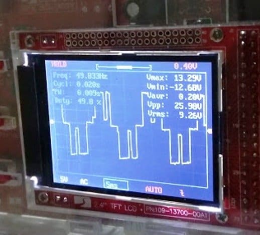
This is the wave measure from the gate side (also from the 555 and 4049 ic): it look just nice. freq and duty cycle almost at desire value.
this is the wave measure from mosfet drain side. everything is mess up. freq and duty cycle are changes.
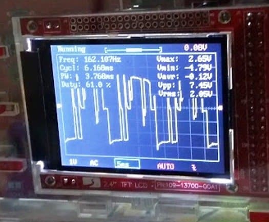
this is i measure from output of my transformer (for testing purpose i used 2A 12v 0 12v - 220v CT).
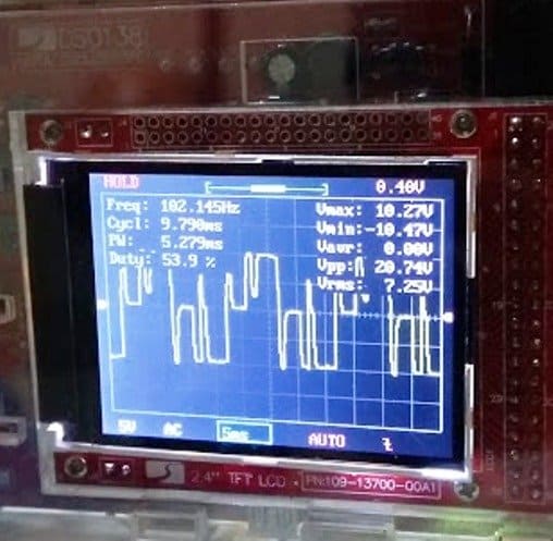
how to get the transformer output wave just like a gate one? i have a ups at home. i try to measuring the gate, drain, and transformer output. the waveform is almost the same on that small ups (modified sinewave). how do i achieve that result in my circuit?
please kindly help, thanks sir.
Solving the Waveform Issue
Hi Rudi,
it's probably happening due to transformer inductive spikes, please try the following:
first increase the 555 frequency a bit more so that the "pillars" across each square wave cycles look uniform and well distributed..may be a 4 pillar cycle would look better and more atable than the present waveform pattern.
connect a large capacitor, may be a 6800uF/35V right across the battery terminals.
connect 12V zener diodes across gate/source of each of the mosfets.
and connect a 0.22uF/400V capacitor across the transformer output winding....and check the response again.


Comments
if I use 6v, 4.5Ah battery than what will be output power……?
Actually I wana make a 100 or 50 w inverter with inbuilt charger using 6v, 4.5 Ah battery plz suggest me the circuit
6V 4.5ah will produce a 15 watt inverter
sir can I use this circuit to get an output of 100w using 6v battery
Shah, yes it will be possible only if your battery is rated at around 25AH or more
Sir moore power to u,i have a question,the built in charger get the power soures to inerter power out put or to the main power electric company
…..from mains electric grid.
Sir can u post a pictur of this circuit with actual parts that already finished instal,,:-) sorry for my another request,,thank u again n more power to u sir,:-)
it's not been tested practically yet, but according to me it's reliable design and will surely work
Sir i have only a little knowlege in electronic symble,i just want to know the kind of parts bisides ot d9 is that a transformer and what is the value thanks u sir i want ur reply soon,,more power to u sir
Thank u sir
Rustico, the part beside R9 is the relay coil which activates the NO, NC contacts when energized or de-energized.
Dear sir,Thanks for useful information.
Please tell me what happen if we not connected 12v truck battery in this circuit,is it(12v battery) for giving solar power at night times ?also give information about cost.
Thanks&Regards
siva
Dear siva, all inverters require battery or a DC input for producing the AC output, without connecting battery the inverter will not operate.
Hi sir…… I want to make home inverter of 2000 VA capacity with in built charger.please suggest me the circuit and give some details.My email id is parasaravalluru@gmail.com. plz help me..
OK, please make the following basic circuit set up first and make it work to produce 100 watts, later I'll explain how to upgrade it to the required 2000 wats.
https://www.homemade-circuits.com/2012/07/simplest-and-best-100-watt-inverter.html
i want to make square wave inverter
Hi RK do you want a square wave inverter or a sine wave inverter??
can i build that circuit on pcb.please post a video regarding construction of given circuit on pcb
sir the output of the 4093 will be square or sine wave
square wave
Hello Sir, this is Larry:
Please sir could you kindly post a circuit on 1000watt (1KVA) inverter.
Thank you in anticipation
hello larry,
i have already have this circuit in my blog, please use the search box to find it.
sir what should be the transformer rating in kva for this inverter
multiply the input voltage and current of the transformer to get results….it will depend on individual needs.
sir,
we connected the schmitt NAND gate circuit using IC4093 (vcc =+12v, vss =gnd) and gave 24v an input to first nand gate N1, through c1 and R8.. we obtained +12v at n4 gate output and 0v for n2 gate. we expect a square wave output. we got a pure dc output… what will be the actual output from the nand gates… please give your valuable suggestions…. as possible we started to do this inverter….. thank you
Nirmal, the connections that you have done looks to be completely incorrect, inspect the diagram carefully and do it exactly as given.
can we use the squarewave directly to domestic loads like fan and light……
yes you can operate lights and fans, just make sure you connect a 0.22uF/600V capacitor across the output of the inveter transformer
sir i want to know how will be the output waveform and the function of each component
hi sir we are going to do ur 400 watts inverter….we want to know how it is working and which technique is used in it
Hi Nirmal, it's a ordinary square wave inverter, I strongly believe that the above design will work, however I have not tested it practically.
yes that can be done…make the stages separately and test them separately before integrating them together.
it can be built by employing more number of transistors and higher wattage transformer
you can use TIP35 or 2N3055 in place of BDY29, mosfets are critical devices and could be very sensitive so I would suggest you to stick with transistors only.
Daniel give me the link of the circuit I'll check it..
Hi sir im Daniel i snt you soo many questioning about the GSM Car Security System but no reply, now i am in the inverter circuit,i want to build the inverter the one that you used (TIP32C) the (1first) question gos to the transformer is the fmer 12-0-12 right? what about the additional wind that show 38v its should be wind 38v or same 12v? (second) can i replace the TIP32 with IRFP250 OR 260 if yes something have be change in the circuit (3rd) its this circuit a pure sine wave or modified sine wave?(4th) can i build this circuit without scope meter,only i have is digital meter.thank you sir im looking forward to hear from you soon.
Hi Daniel,
I have already provided more than enough data in the car GSM article therefore I have stopped answering to comments under that article. The project is strictly for the experts in the field so anyway there's no point in making that project if you are not an expert.
Which inverter circuit are you referring to?
pls provide the link.
Thanks very much, if you could not build a simple Low Battery Cut-off and Overload Protection, it means you are very new in the field and therefore could drastically fail with the above circuit also, because the above circuit is much much difficult.
try something simple, may be you can begin with the following design for learning:
https://www.homemade-circuits.com/2012/09/mini-50-watt-mosfet-inverter-circuit.html
this is the excellent work you are doing, sir, i just want to know i have some old ups , like 600va etc. can i use its transformer in the above circuit
thanks Gowhar!
Yes you can use it.
Sir
Though I know a little of electronics my knowledge is very limited.On seeing your " how to make a 400 Watt inverter I am tempted to try to do this. kindly guide about
inv on,p1,n/i n/o.What components I have to fit in there & their values.My email address is pramamurthister@gmail.com. Thanking you
INV ON is the LED.
P1 is a variable resistor or a preset.
N/O and N/C are the relay contacts.
Please note that the above circuit is not for newcomers, there's a big chance that you may fail to make it work due to lack of complete knowledge.
Dear Sir
i am a student a i want to connect my on 400w inverter circuit in my project pls i nit assistance from you sir.
Dear Sadiq,
what help do you need?
It is a square wave design