MPPT stands for maximum power point tracker, which is an electronic system designed for optimizing the varying power output from a solar panel module such that the connected battery exploits the maximum available power from the solar panel.
Introduction
NOTE: The discussed MPPT circuits in this post do not employ the conventional control methods like "Perturb and observe", "Incremental conductance, "Current sweep", "Constant voltage"......etc etc...Rather here we concentrate and try implementing a couple of basic things:
- To make sure that the input "wattage" from the solar panel is always equal to the output "wattage" reaching the load.
- The "knee voltage" is never disturbed by the load and the panel's MPPT zone is efficiently maintained.
What's Knee Voltage and Current of a Panel:
Put simply, the knee voltage is the "open circuit voltage" level of the panel, while the knee current is the "short circuit current" measure of the panel at any given instant.
If the above two are maintained as far as possible, the load could be assumed to be getting the MPPT power throughout its operation.
Before we Delve into the Proposed Designs, let's first get acquainted with some of the basic facts regarding solar battery charging
We know that the output from a solar panel is directly proportional to the degree of the incident sunlight, and also the ambient temperature. When the sun rays are perpendicular to the solar panel, it generates the maximum amount of voltage, and deteriorates as the angle shifts away from 90 degrees The atmospheric temperature around the panel also affects the efficiency of the panel, which falls with increase in the temperature.
Therefore we may conclude that when the sun rays are near to 90 degrees over the panel and when the temperature is around 30 degrees, the efficiency of the panel is toward maximum, the rate decreases as the above two parameters drift away from their rated values.
The above voltage is generally used for charging a battery, a lead acid battery, which in turn is used for operating an inverter. However just as the solar panel has its own operating criteria, the battery too is no less and offers some strict conditions for getting optimally charged.
The conditions are, the battery must be charged at relatively higher current initially which must be gradually decreased to almost zero when the battery attains a voltage 15% higher than its normal rating.
Assuming a fully discharged 12V battery, with a voltage anywhere around 11.5V, may be charged at around C/2 rate initially (C=AH of the battery), this will start filling the battery relatively quickly and will pull its voltage to may be around 13V within a couple of hours.
At this point the current should be automatically reduced to say C/5 rate, this will again help to keep the fast charging pace without damaging the battery and raise its voltage to around 13.5V within the next 1 hour.
Following the above steps, now the current may be further reduced to C/10 rate which makes sure the charging rate and the pace does not slow down.
Finally when the battery voltage reaches around 14.3V, the process may be reduced to a C/50 rate which almost stops the charging process yet restricts the charge from falling to lower levels.
The entire process charges a deep discharged battery within a span of 6 hours without affecting the life of the battery.
An MPPT is employed exactly for ensuring that the above procedure is extracted optimally from a particular solar panel.
A solar panel may be unable to provide high current outputs but it definitely is able to provide with higher voltages.
The trick would be to convert the higher voltage levels to higher current levels through appropriate optimization of the solar panel output.
Now since the conversions of a higher voltage to higher current and vice versa can be implemented only through buck boost converters, an innovative method (although a bit bulky) would be to use a variable inductor circuit wherein the inductor would have many switchable taps, these taps may be toggled by a switching circuit in response to the varying sunlight so that the output to the load always remains constant regardless of the sun sunshine.
The concept may be understood by referring to the following diagram:
Circuit Diagram
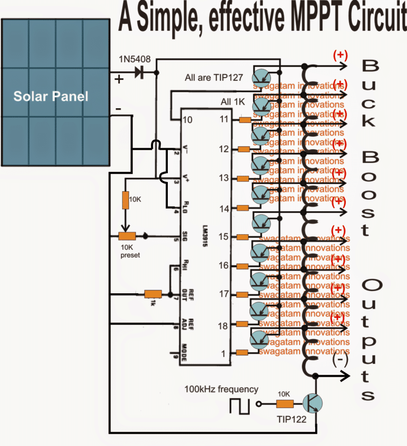
Using LM3915 as the Main Processor IC
The main processor in the above diagram is the IC LM3915 which switches its output pinout sequentially from the top to the bottom in response to the diminishing sun light
These outputs can be seen configured with switching power transistors which are in turn connected with the various taps of a ferrite single long inductor coil.
The lower most end of the inductor can be seen attached with a NPN power transistor which is switched at around 100kHz frequency from an externally configured oscillator circuit.
The power transistors connected with the outputs of the IC switch in response to the sequencing IC outputs, connecting the appropriate taps of the inductor with the panel voltage and the 100kHz frequency.
This inductor turns are appropriately calculated such that its various taps become compatible with the panel voltage as these are switched by the IC output driver stages.
Thus the proceedings make sure that while the sun intensity and the voltage drops, it's appropriately linked with the relevant tap of the inductor maintaining almost a constant voltage across all the given taps, as per their calculated ratings.
So I have explained the functioning with the help of the following scenario:
Suppose the coil is selected to be compatible with a 30V solar panel, therefore at peak sunshine let's assume that the upper most power transistor is switched ON by the IC which subjects the entire coil to oscillate, this allows the entire 30V to be available across the extreme ends of the coil.
Now suppose the sunlight drops by 3V and reduces its output to 27V, this is quickly sensed by the IC such that the first transistor from the top now switches OFF and the second transistor in the sequence switches ON.
The above action selects the second tap (27V tap) of the inductor from top executing a matching inductor tap to voltage response making sure that the coil oscillates optimally with the reduced voltage...similarly, now as the sunlight voltage drops further the respective transistors "shake hands" with the relevant inductor taps ensuring a perfect matching and efficient switching of the inductor, corresponding to the available solar voltages.
Due to the above matched response between the solar panel and the switching buck/boost inductor...the tap voltages over the relevant points can be assumed to maintain a constant voltage through out the day regardless of the sunlight situation....
For example suppose if the inductor is designed to produce 30V at the topmost tap followed by 27V, 24V, 21V, 18V, 15V, 12V, 9V, 6V, 3V, 0V across the subsequent taps, then all these voltages could be assumed to be constant over these taps regardless of the sunlight levels.
Also please remember that these voltage can be altered as per user specs for achieving higher or lower voltages than the panel voltage.
The above circuit can also be configured in the flyback topoogy as shown below:
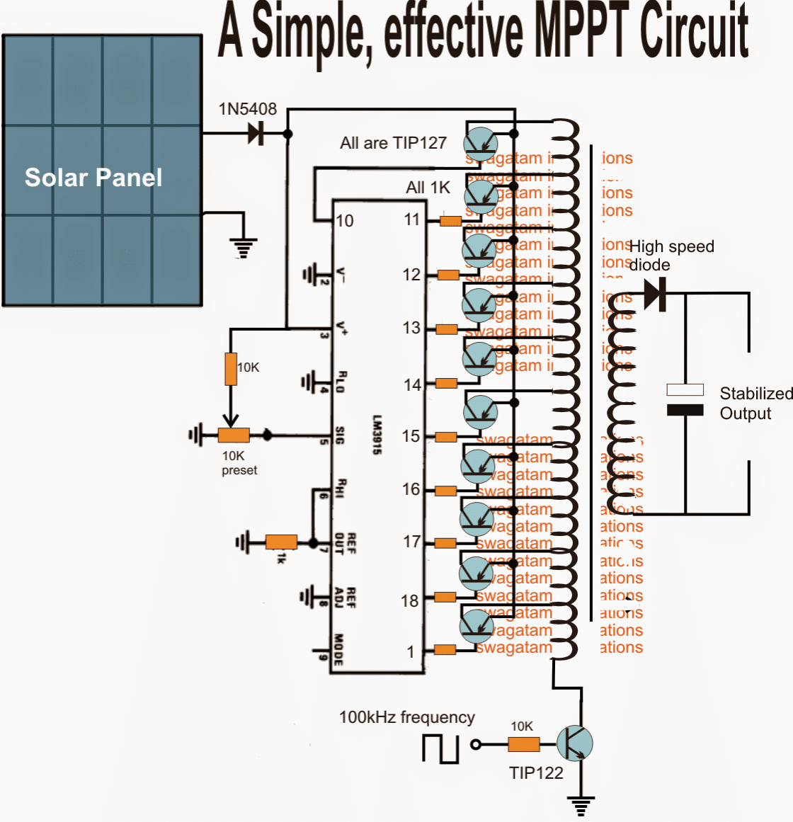
In both the above configurations, the output is supposed to remain constant and stable in terms of voltage and wattage regardless of the solar output.
Using I/V Tracking Method
The following circuit concept ensures that the MPPT level of the panel is never disturbed drastically by the load.
The circuit tracks the MPPT "knee" level of the panel and makes sure that the load is not allowed to consume anything more which might cause a dropping in this knee level of the panel.
I have explained how this can can done using a simple single opamp I/V tracking circuit.
Please note that the designs which are without a buck converter will never be able to optimize the excess voltage into equivalent current for the load, and might fail in this regard, which is considered as the crucial feature of any MPPT design.
A very simple yet effective MPPT type device can be made by employing a LM338 IC and an opamps.
In this concept which is designed by me, the op amp is configured in such a way that it keeps recording the instantaneous MPP data of the panel and compares it with the instantaneous load consumption. If it finds the load consumption exceeding this stored data, it cuts off the load...
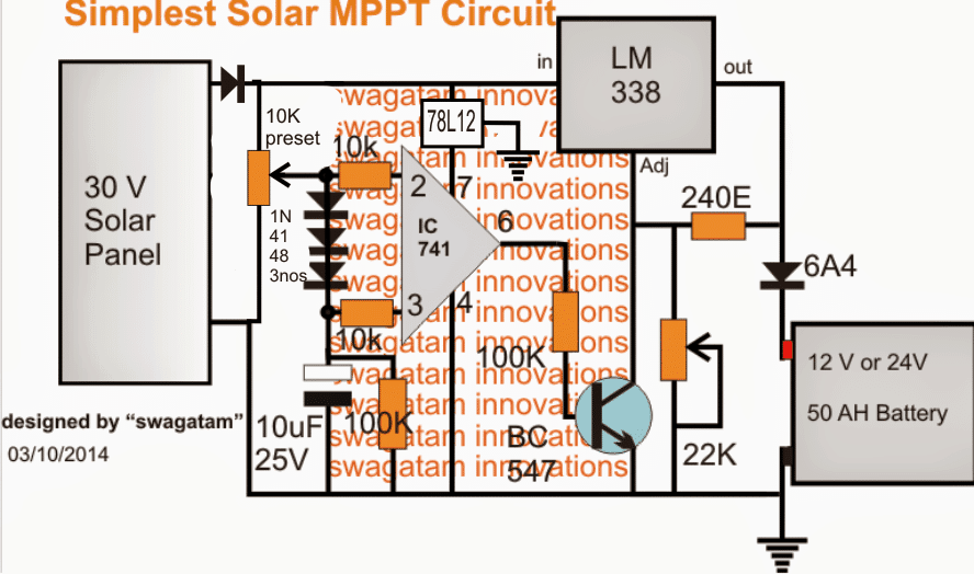
The IC 741 stage is the solar tracker section and forms the heart of the entire design.
The solar panel voltage is fed to the inverting pin2 of the IC, while the the same is applied to the non-inverting pin3 with a drop of around 2 V using three 1N4148 diodes in series.
The above situation consistently keeps the pin3 of the IC a shade lower than pin2 ensuring a zero voltage across the output pin6 of the IC.
However in an event of an inefficient overload, such as a mismatched battery or a high current battery, the solar panel voltage tends to get pulled down by the load. When this happens pin2 voltage also begins dropping, however due to the presence of the 10uF capacitor at pin3, its potential stays solid and does not respond to the above drop.
The situation instantly forces pin3 to go high than pin2, which in turn toggles pin6 high, switching ON the BJT BC547.
BC547 now immediately disables LM338 cutting off the voltage to the battery, the cycle keeps switching at a rapid pace depending upon the IC's rated speed.
The above operations make sure that the solar panel voltage never drops or gets pulled down by the load, maintaining an MPPT like condition throughout.
Since a linear IC LM338 is used, the circuit could be yet again a bit inefficient....the remedy is to replace the LM338 stage with a buck converter...that would make the design extremely versatile and comparable to a true MPPT.
Below shown is an MPPT circuit using a buck converter topology, now the design makes a lot of sense and looks much closer to a true MPPT
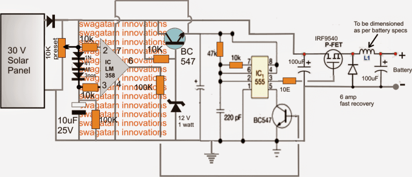
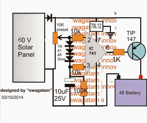
48V MPPT Circuit
The above simple MPPT circuits can be also modified for implementing high voltage battery charging, such as the following 48V battery MPPT charger circuit.
The ideas are all exclusively developed by me.



Discussion & Solutions
hi sir,how are you?actually i want to know i am already using a pwm based solar charger with my inverter.but want to use MPPT.can you publish a cicuit which can handle 24v 30 amp. thanks
Hi Ravi,
I'll try to design it for you, however making the SMPS part in the MPPT can be little difficult, if I succeed I'll post it here for you.
thanks sir,can i divide the circuit in 2 part in first part the battery will be directly connected to the solar and in the evening and before noon a voltage amplifier will increase the volt to a desired level.is it possible?
Yes you can do it, the following two circuits can be combined to produce the intended effects:
https://www.homemade-circuits.com/2013/04/simple-solar-mppt-circuit-using-ic555.html
https://www.homemade-circuits.com/2013/06/universal-ic-555-buck-boost-circuit.html
Then it may be fairest to be honest about that.
NONE of the circuits that you label as such, are actually MPPTs, as none of them will transfer maximum power to their load (the battery). If you want a cheap and easy way to non-MPPT charge a battery, you could suffice with a diode between solar panel and battery, perhaps with a relay or MOSFET to turn of charging once the battery is full. This will work better than any of the designs you've posted.
Misinformation is worse than no information at all. Two project teams at my school have attempted to use your designs as a basis for their MPPT, only to lose valuable time and resources before finding they don't work as advertised.They now risk failing their course, as we don't give them a passing grade if they can't demonstrate MPPT functionality. (They have learned a valuable lesson — don't just trust any information you find on the Internet…)
I don't blame you for this comment because may be you yourself are much ill informed about electronics and might have failed to understand the above circuit details.
The above mppt cannot be considered a real mppt only because it doesn't employ I/V curve tracking but that doesn't take away its credit of being extremely efficient than the ordinary solar chargers that you are referring to.
How much do school students know about electronics and how much experience do they have this such field? I have seen experienced hobbyists consulting me for days and multiple failures until finally I make them succeed in making a particular project.
If your students couldn't make this simple looking solar optimizer then imagine what they would do with an actual mppt.
People appreciate me for providing alternate innovations, concepts, inventions that are easier and much effective.
It's unfortunate that there are folks who like to break their frustrations on creative helping engineers like me who are very rare online.
If you are unable to understand a concept you better quit instead of criticizing it due to your own inefficiency.
…if anybody points out faults in my designed circuits I would welcome that, but just criticizing blindly could be foolish..
Hi. Great site.
I agree with the mppt concept. We live completely of grid. We have 8 x 240w 24v solar panels connected with 4 x 40a 24v pwm controllers to batteries and a 3kw wind turbine. Power to the house is done via 3kw pure sine wave inverter. My idea is to connect a simple mppt circuit infront of my pwm controllers. Do you think this will enhance the solar panels charge rate, more important in early mornings and late afternoons.
If so can you please help with a simple design for 24v 40a mppt circuit than can installed in front of my pwm controllers.
Thanks
If so
Hi, Thanks!
It will depend on how the PWM controllers are configured.
I am assuming the connected batteries to be rated at 12V and the PWM controllers generating the required 14V for charging these batteries.
If this is so, then I think the PWM controllers would itself be quite efficient in optimizing the solar panel current, and external MPpTs wouldn't be required.
Hi
No sorry we have 24V battery bank. The PWM's are charging at 28.8V. My solar panels open V are +- 40V, I think it would be better to install a dc – dc converter in front of the PWM controller to change the higher volts low amp to lower volt higher amp. Can a converter be made with high current +-40A.
Thanks
Yes, you can try a buck converter using a IC555 circuit, connect it in between the pwm converter and the solar panel, one suitable design can be understood here:
https://www.homemade-circuits.com/2013/06/universal-ic-555-buck-boost-circuit.html
hi i am planning to connect this mppt circuit io dual axis solar tracker.
1) if my solar pannel rating is 50w what must be the R1,R2,R3 values
2) Are the relays in this circuit are 12v 8 pin relay
3)In the circuit an arrow pointing 10k resistor, is this resistor variable 10k resistor
4) in the circuit the connecting wires are disconnected in some places how the wires connected there
1) resistor values will depend on the battery AH rating.
2)relays are 12v 5 pin, spdt
3)those are presets or trimpots
4) the gap indicates that the overlapping wires are not connected in anyway.
hi!
thanks a lot in helping me in completing the dual axis solar tracker it's working perfectly
my next step is to connect the solar panel of dual axis solar tracker to this simple mppt circuit
is this idea good
Here in the circuit A3 and A4 are the other 1/2 of IC 324 then in circuit A3 is +v and ground connection are these connections pin 4 and 11 in IC 324?
You are welcome!
The IC 324 has four quad opamps in one package, the supply for the entire IC is at the pins 4 and 11.
I would recommend the simpler zero drop charger design which is shown below, it's basically a voltage regulator circuit that optimizes the solar parameters and avoids unnecessary loading of the panel.
https://www.homemade-circuits.com/2013/08/simple-zero-drop-solar-charger-circuit.html
In the circuit one transistor base is connected to 100 ohms and after that an a connection with big dot is left freely what to connect there?
ignore the dot, remove it from the circuit, it's a drawing mistake.
1) R1 R2 and R3 = 0.7/ charging rate in kilo ohms or ohms?
2) Is 4K7 is preset resistor?
1) it's in Ohms.
2)4k7 can be a preset or a pot. It should be a 10k preset/pot actually
when will the red and green led's glow?
green = charging
red = batt full.
How to set the 10k preset values explain briefly?
pls make the circuit first, then I'll explain it further.
Where the ground in the circuit conneted?
transistor emitter lines need to be connected together
i made the circuit,but my solar panel is giving 10 volts without mppt but when the mppt is connected only 6 volts is measured. I measured this 6v by taking away the battery and connected a multimeter in place of battery it showed 6 volts. how can maximum power can be obtained with reduced voltage.
i connected 3 w 9v solar pannel and 12v 1.3AH battery
and the red led is always glowing even when the battery is dischearging
how can you charge a 12V batt with a 9v input?????
you will need a 18v panel for a 12v batt and the above circuit.
also replace the 4k7 pot under LM38 with a 10k pot for getting a 15V adjustable range
Does it mean both the transistor emitter points should be connected
yes.
The ground points must be connected to battery -ve or solar panel – ve
battery negative
Why that much high rating 10 amp diode is used?
So that bigger batteries upto 100ah can be charged, you can use smaller diodes suiting your requirements.
sir gud day,
thank you for your informative and helpful blog.
my some question is:
1.in R1,2,3 0.7ohms, how many watts i apply if my battery is 12v 40AH and my solar panel is 50w, 12v-20v. pls.. give me exact value of the resistor 1,2,3.
2.IC324 is it also LM324 if i buy in elect. store.
3.all 4 presets 10k parts under ic324 is it automatically set already or i manually configuring the value to set the right output, if manually do, will you mind how to set this in correct value.
Hope you appreciated me. Thanks very much!
The above circuit procedures could be quite complicated for anyone who may new in the field, it's for the experts….I'll try to update the article soon with an identical design but using lesser number of components and hassle free setting procedures….so please keep in touch until then
your designed circuit is not a true MPPT circuit, as expressed by JD Bakker. You fault him, but your headline is for an MPPT controller, which the circuit is not. As we say in America, that's false advertising.
Rather than just criticize, I will point you to a solution. Review the simple MPPT controller based on the Linear Technology LT3652. Quite an easy circuit to construct, actually MUCH easier than yours. Maybe instead of getting defensive, you should look for a true solution. You could also provide instructions to help enhance output capacity (charge current).
….and how would anybody charge a 100AH or a 200AH batt using LT3652
sir can u design the above solar charge controller for 48V 15A current level for MPPT tracking
Mayuresh, you can try the last circuit updated in the above article.
Sir what is the value of the capacitor C in the middle of the circuit? its connected in the emitter of the BC547.
slide, please click the diagram to enlarge it….you'll find it to be 220pF
sir in your other pic for this project there is no trimmer atach
jeffery please provide me with the link, I'll check it out
Hai sir,
I have two 35v165w panel. Can u use this circuit for charging 12v 100AH Battey ?
Hi Ajith, you can try the last circuit which is the simplest one, make sure to add a 6V zener in series with the base of the transistor.
connect the panels in parallel.
Sir,
U mean 48v mppt controller circuit ?
Which diode connected in series with panel ?
yes that's correct, use a 10amp diode with the panel.
Sir,
I am build the ciruit, but the output voltage is around 35 v , what I do ?
Ajith, did you set the circuit as directed in the article.
connect an LED in series with the emitter of the transistor, and switch ON the 35V input
next, without connecting any battery first adjust the preset such that the voltage at pin2 is 12V,
without any load this LED should stay switched OFF.
Now short the output terminals, LEd should light up now.
confirm the above and let me know.