You may have often wondered whether it was feasible to get higher voltages than 12 V from a 7812 IC? In this short post I have explained how to configure the IC 7812 with a BJT stage, so that its output can be made variable for achieving any desired voltage higher than 12 V, without compromising the performance of the 7812 IC.
A 7812 IC is a 3 terminal fixed voltage regulator device which is able to produce a constant 12 V output in response to an input Dc between 15 V and 30 V.
It is sometimes essential to set up this type of 3-terminal voltage regulator IC to provide an increased output voltage than the fixed value through the regulator itself.
How the Circuit Works
The standard method of getting a higher voltage output from a 7812 IC is to hook up the ''common'' terminal of the IC to the junction of a resistive divider installed across the regulated output supply positive and ground.
The regulator voltage at this point appears over the upper divider resistor; thus, in case for example identical divider resistors are used, the output voltage becomes two times more than the value managed by the regulator across its common terminal and output terminal.
The issue using this technique is that a lot of IC regulators (eg the 78XX series) include a tiny quiescent current (around 10mA) moving out through their common terminal towards ground. The value of this current is not tightly governed, and therefore the total output voltage tends to become a little bit erratic because of this extra current streaming within the lower half of the resistor divider.
Low value resistive divider seems to solve the problem, but this may up end up with more complications such as heat dissipation and reduced efficiency.
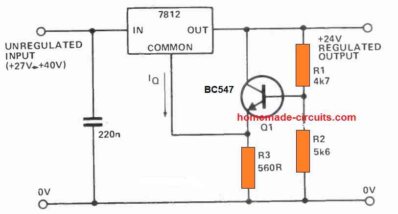
The circuit above eliminates the challenge through the use of transistor Q1 to crank out a low impedance on the regulator common terminal through its emitter-follower configuration.
The transistor emitter transfers the voltage derived from a relatively high-resistance divider network connected across the base of the transistor.
The value of R3 is not crucial, however should be sufficiently small in order to enable the maximum possible quiescent current from the ground terminal of the 7812 IC, without resulting in Q1 to switch off. The circuit exhibits a functional 24 Volt supply through a 7812 regulator.
A desired higher output voltage from the IC 7812 can be adjusted by altering the values of R1 and R2 accordingly.


Comments
I am using a TPA 3II6 D2.
I STEREO CHANNEL IS GREAT, WITH SUB WORKING PERFECTLY.
The other channel is rather low and distorts baldy. I have
changed both i.c.’s 5332 but still distorts.
I am suspecting one of the main i.c.’s
I am using 12-0 -12 2 amp center
Tapped.
Your valued guidance is very necessary. Thank You VERY much!!
Aubrey
I haven’t used this IC yet, moreover without checking the circuit physically it can be difficult to judge the fault.
Hi I am Paul , I was making a miniproject on audio amplifiers and when I similated it it never worked . My equipments are 555ic with a transformer as the input of audio
Which circuit are you referring to?
Dear Swagatam, hello
I thank you kind man very much for all your favor
Wish you the best
Best regards
Sam
You are most welcome Sam!
Dear Swagatam, hello
Thank you very much for letting me know about the maximum input voltage of 7812, also your so soon and complete answer to all my questions. Thus am I able to reach the higher current by adding more 7812 in parallel with the one in this circuit ? I have seen the related circuit in your site before.
Is it possible to replace 7812 with 7805
Wish you the best dear Sir
Best regards
Sam
Please kindly discard my before mail
You are welcome Sam,
Yes you can add more numbers of 7812 in parallel to get more current, just make sure to put them on a common heatsink and very close to each other.
Yes 7805 can be replaced with 7812.
Dear Swagatam
Hope you are glad and healthy.
As it is mentioned in the text, max input of 7812 is 30v while the value of 40v is mistakenly printed in the circuit diagram.
Just 3 questions: If I decide to have a variable regulator between 12 and 30; as the title of the article implies, am I allowed to use variable resistors for R1 and R2 and what would be the values of these two resistors?
What is your suggestion for substituting high current transistor instead of BC547? would you please name a few ones? Is it necessary to change some components in order to have higher current?
Thank you so much for you kind attention
Best regards
Sam
Dear Sam,
The max input to the IC can be upto 40V, but it is safer to restrict this to 30V.
You can get a variable output by replacing R2 with a variable 10K pot.
The transistor has no relation to current, it only sets the output voltage.
You can get a maximum current of 1 amp from this circuit.
Hi Swagatham
Yes thanks for sharing your ideas about the 7812 voltage regulator making it a variable output , I will try out the circuits you have shown in your article
Also thanks for sharing how to check an unknown zener value and arrive at getting the value by connecting the zener diode in question in series with a 1 K resistor to a DC supply and checking the voltage across the zener,
What I did is I connected a variable voltage supply across the zener & resistor (1K or even 2K ) from 1.5 volts to 30 volts and gradually increased the voltage at the same time measuring the voltage across the zener when the voltage remains constant across the zener that is the zener voltage and at this point when you measure the voltage across the resistor it shows the balance or the shared voltage …… say I applied 25 volts across the combination if it stops at 12 volts at the zener, it a 12 V zener, then it would read 13 volts across the resistor
If you think this is right what I did let me know or please advise
Thanks Swagatham & all the best to you
Regards
Vee
Thank you, Vee,
I appreciate your response.
Your are absolutely correct with your assumptions, an unknown zener diode must be checked exactly as explained by you.
All the best to you!
Mr. Swagatam 7812 integrated number 2 foot I connect the zener diode takes care of the event. For example, if I connect a 1.5-volt zener, I get an extremely stable 13.5-Volt output. At lower voltages, I connect 1N4007 or install an adjustable resistor, capturing the voltage I want.
Thank you for the feedback Mehmet, I agree with you zeners can be also used, however in the above design we can change the resistor values to get any desired output voltage between 12 V and 30 V
Hello, You have posted your question under the wrong article. The above article is about 7812 IC, not battery charger. Please post it under a battery charger circuit I will try to figure it out!