Free Energy is available all around us in a variety of different forms, it just needs to be appropriately harnessed and used. One such example is our modern streets and roads where thousands of heavy and small vehicles pass everyday non-stop.
Electricity from Roads
The amount of energy transferred across the roads by these vehicles could be huge, and easily tapped, especially over the speed breakers where it's much easily accessible. The procedure and the circuit diagram are enclosed herein.

If correctly implemented, generating electricity from a road speed breaker could be actually very straightforward and a permanent source of electricity.
The investment behind it is relatively lower compared to the long term free energy potentials it ensures.
We know that when vehicles step over a speed breaker, it slows down until it has entirely crossed the construction.
Through an appropriate arrangement, the speed breaker hump could be installed with a spring loaded mechanisms which could aid the speed breaking requirement and also absorb the energy from the vehicle movement such that the resultant produces free collectible energy right underneath the speed breaker location.
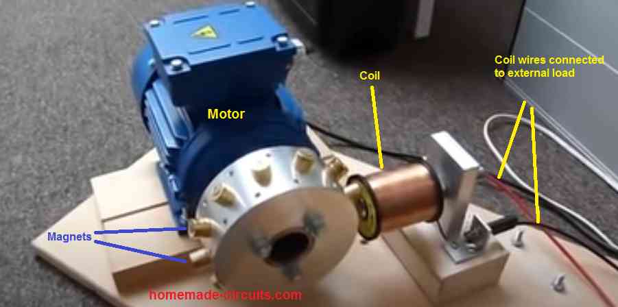
The conversion could be easily and effectively done through age old traditional method, that is by using a motor generator system.
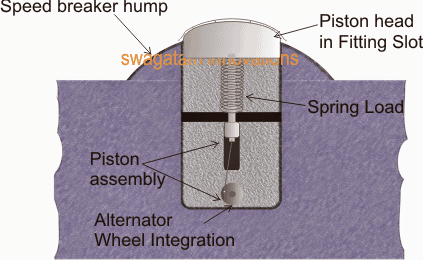
The Piston Mechanism
An example image could be seen below. It shows a piston mechanism where the head surface circumference of the piston coincides with the speed breaker hump curve. This piston head is secured and positioned slightly raised above the speed breaker hump so that the vehicle is able to hit and push it down while passing over it.
The piston is fitted with a spring loaded shaft appropriately installed in a concrete cavity constructed just below the hump.
The piston can be further seen clamped with an alternator wheel such that the perpendicular movement of the piston produces a rotational movement over the connected wheel and the alternator shaft.
How the Generator Works
Whenever a vehicle climbs and passes over the speed breaker, the piston is pushed down, thrusting a rotational movement over the connected alternator shaft. This happens for as many times a vehicles crosses the speed breaker hump.
The above action is converted into the generation of electricity from the alternator which is appropriately conditioned using a boost converter stage for making the output compatible with the associated battery specification, so that it's charged optimally during the process.
Many such mechanisms may be placed in row across the entire speed breaker length for harnessing the entire section of the area.
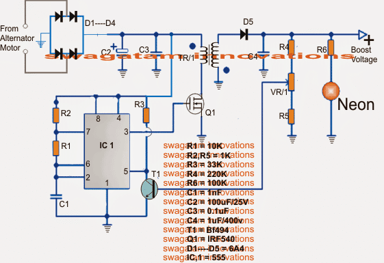
Circuit Diagram
The above discussion explained the mechanical implementation of the proposed speed breaker electricity generation concept.
Using a Boost Converter for Charging Battery
The following section explains a simple boost converter circuit which may be used in conjunction with the above for acquiring a well optimized voltage/current for the charging of the connected battery bank.
The circuit is simple, wired around our friendly IC 555 which is configured as an astable multivibrator with a high frequency determined by R1/R2/C1.
The received voltage pulses from the alternator is first rectified and filtered by D1---D4 and C2.
The stabilized voltage is then fed to the 555 stage which converts it into a high frequency output across the gate/source of the driver mosfet stage.
The mosfet oscillates at the same frequency and forces the entire current to oscillate through the primary of the associated boost transformer.
The transformer responds by converting the primary current induction into the corresponding high voltage at its secondary winding.
The amplified voltage is next rectified and filtered by D5/C4 for the required integrations.
A feedback link could be seen via a VR1 preset control to the base of T3. The arrangement could be used for tailoring the output voltage to any desired level by suitably adjusting this preset.
Once it's set, T3 makes sure the output level does not cross this level by grounding control pin#5 of the IC 555 for the same.
The energy stored inside the batteries through the above speed breaker electricity generation could be further used for operating an inverter or directly for illuminating street lights (LED lights for more efficiency)
The Flyback Converter Circuit
The Boost Inductor Specifications
The ferrite transformer TR1 could be made over a suitable torroid ferrite core which fits the best for your application considering the amp output.
An example image may be witnessed below, the primary is dimensioned for a 5V/10amp input, while the secondary for yielding about 50V at 1 amp.


Comments
Hi, what’s the efficiency of the boost converter? Is the boost converter operating in CCM or DCM. I am trying to understand the circuit better, especially the boost convertor properties like duty ratio etc.
Hi, the exact specifications of the boost converter are not known to me, The CCM, DCM can be easily tweaked using an oscilloscope and by adjusting the PWM function (R1) of the IC 555…
Thank you sir, I just found out a circuit fitting my need.
OK great!
I am really sorry that I can’t reveal further details of the project due to certain guidelines.
Hi Sir,
I haven’t designed the booster part yet. I completed the circuit for certain other parts….for full completion of the project I needed a booster circuit.
I got the design for a 240V boost converter for 10V to 48V input in this link
http://www.analog.com/en/design-center/reference-designs/circuit-collections/lt8331-10v-to-48v-input-240v-boost-converter.html
I am still unsure about the cost, accuracy and size of this device.
Hi SST, you said you were not getting a stable voltage at the output, and that’s why I wanted to know the circuit details without which it would be difficult for me to solve your problem.
yes the linked design should be accurate enough, although the current seems to be very low.
Hi Sir,
Is there any way to obtain a constant output from an input that is fluctuating between 100V AC and 220V AC.
I need a compact circuit, as the project that I am working on has already increased in size.
Hi SST, can you tell me which kind of circuit did you use? is it a boost converter using a ferrite core?
for a compact design I would recommend a flyback boost converter circuit, you can search online for “12V to 220V flyback converter circuit”, you may find many options
Since I am going to rectify the output, will frequency be a serious factor.
here frequency is related to inductor turn count and switching efficiency, if frequency is not correctly optimized will lead to heating up of the mosfet and wastage of energy that’s why it is important
Hi Sir,
If I make suitable changes to this circuit given in the link below can I get 240V AC, will rectifying it give 240V DC, and is this circuit accurate enough.
https://www.homemade-circuits.com/how-to-convert-12v-dc-to-220v-ac-using/
Hi sst, yes it work, but might need some serious tweaking with the coil and the output setting, I would recommend to first make it and test without the output feedback loop, if you succeed in getting above 250V then you can try the feedback link for controlling the output, I am not sure about its accuracy because accuracy will depend on the selection of inductor and the frequency with perfect calculations, which can be a little complex
I have referred this website for the diagram and design procedures
I am not sure what to do with the gate of the thyristor. Suppose if I am using a transistor, can it be used for high power application.
The switch cannot be an SCR, it will need to be a transistor, then it will work.
Hi Sir,
Will it be possible to design a 24V DC to 240V Dc Boost converter, just by using inductors, capacitors, resistors and SCR-TYN610M. I did a theoretical design and I found out the value for inductor to be 1.8mH which is quite compact. Please do look into this.
Hi SST, as far as I know an SCR cannot be used as a switching device for a DC input, If you have a better idea please let me know. Although, it may be possible with a transistor, as explained in this article:
https://www.homemade-circuits.com/how-to-make-simple-boost-converter-circuits/