In this post I have explained a 12V power supply with battery charger circuit which can be implemented as an uninterruptible emergency heating system for incubator chambers. The idea was requested by Mr. Arya.
Technical Specifications
I've read all your good article, but can you help me to design an Linear PSU that provide 12 vdc 5A output from 220vac, but it must also charge a 60Ah Lead Acid car battery at 5Ah, but when emergency blackout (no 220vac supply) DPDT relay will switch to use battery to light 50watt 12vdc light bulb for incubator heater and it's 12vdc electronic thermostat.
when 220vac supply on again dpdt switch will use PSU to light heater, and the will charge the battery.
this is my available electronic component in my inventory:
1. 1x Big Trafo 220v to 30v 25Amps
2. 1x LM317T IC
3. 2x 7812 IC
4. 4x TIP41C
5. 2x 2N3055
and assorted diodes and resistor and of course i have 2 dpdt relay
i also have few mosfets like IRF540, and 18N50, but i don't know how to use it.
i also have 4 of, 5 watt 0,1 ohm resistor, and the charger that I wanted to build, can it have automatic cut off, so I can leave the battery forever on the unit, and all of that spare parts that I already mentioned before was salvaged material, but has been tested and everything was seems OK, for the small capacitor i can manage to find it, if there are any.
The transformer that i mentioned before already have 25 v 3300uF capacitor, and it's big 30 Amps rectifier( it's look like 4 legged transistor that have a sign look like this - ~ ~ + is that right?, a rectifier?) both of it soldered with cables, near the trafo.
Lights out in Indonesia is often, especially here in eastern Indonesia, in Mollucas Islands.
Thank you before sir. Arya.
The Design
The idea is intended to ensure an uninterrupted supply of warmth to an incubator chamber regardless of the presence or absence of the mains grid voltage.
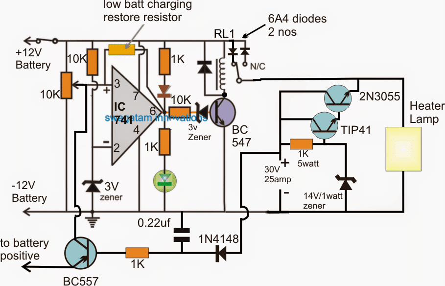
Referring to the above design of the proposed emergency incubator lamp with charger circuit, we can see a straightforward layout consisting of a transistorized voltage regulator stage formed by a Darlington paired 2N3055/TIP41 BJTs and an opamp based battery over voltage, lower voltage cut off stage.
The indicated 30V input DC is derived from the mentioned 30V 25amp transformer after appropriately rectifying it via a bridge rectifier and a filter capacitor (3300uF).
The fed input is processed by the Darlington BJT stage and an approximately 14V is achieved across the emitter of the 2N3005 transistor at a particular current level determined by the 1k resistor at the base of the TIP41 transistor. This resistor may be increased or decreased for proportionately increasing or decreasing the emitter current of the 2N3055.
The above regulated output is used to power the incubator heater lamp and also to charge the associated 12V 60AH battery.
How the Circuit Functions
As long as the battery voltage is below the optimal full charge level, the red LED at pin6 of the opamp 741 remains illuminated and the green LED stays switched OFF.
The above situation keeps the BC547 and the connected relay toggled OFF, which allows the DC voltage from the 2N3055 emitter to pass to the battery via the N/C contact of the relay and via the respective 6amp diode connected at the N/C of the relay.
Once the battery is fully charged, the red LED switches OFF, the green LED is turned ON , so does the BC547 transistor and the relay.
The relay contact now shifts from its N/C to N/O, cutting off the charging supply to the battery, and preventing any chance of over charging for the battery.
The above action also enables the battery voltage to reach the heater lamp via the N/O contact and the series diode at the N/O contact.
However the explained scenario has a problem.....here the changeover action from mains to battery may be inhibited whenever the battery may be in the charging mode.
Because during the charging phase the battery voltage would be somewhere within the full charge and low charge value, maintaining the relay contacts towards the N/C position which in turn would prevent the battery voltage from reaching the heater lamp.
In order to rectify the above issue a BC557 can be seen introduced, which makes sure that each time mains fails and the relay is at the N/C, it's forced to revert to the N/O position and hold this until the battery level falls below the predetermined unsafe low voltage level.


Comments
@Were you able to put the circuit together? How many hours does it last?