A simple earth leakage indicator circuit discussed here can be used for getting some very useful results regarding current leakages from an appliance body into the earth pin. The idea was requested by Mr. SS kopparthy.
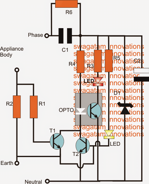
The circuit of the proposed earth leakage indicator is shown in the figure below.
Each such unit may be used for individual appliances having earth pins, or a single circuit may be placed near the MCB for detecting a possible common leakage from all the appliances.The circuit may be understood with the points I have explained below:
Circuit Operation
R2 is positioned as a current sensing resistor which should have a relatively low value so that the actual earthing feature doesn't get obstructed due to its resistance.
T1 here forms a current sensing and a voltage amplifier stage. The detected small voltage across R2 is quickly amplified by T1 and fed to the LED inside an opto coupler.
As long as the leakage is not relatively significant (below 20mA) the LED inside the opto does not respond, however the moment this value exceeds the set limit, the LED inside the opto illuminates switching ON the corresponding built-in transistor, which in turn actuates the red LED connected across its collector and positive lead indicating a possible earth leakage.
The supply for the entire operation is derived through a small trasformerless power supply using C1, D1, C2 as its main components.
The red LED may be replaced with a 12V piezo buzzer for getting an audio indication, or both may be used in parallel for facilitating a dual mode indication.
The value of R2 may be calculated using the following formula:
R = 0.2/I. where I is allowable current leakage through the earthing cable, assuming this to be 20mA we can calculate it as:
R = 0.2/.02 = 10 ohms
Since the collector resistance if T1 is quite high, T1 could get triggered with as low as 0.2 across its base/emitter, that's the reason why 0.2 is selected in the above formula.
The T2 stage is introduced for monitoring the "health" of the earthing connection, as long as it's at par with the neutral, T2 stays switched off since its base remains grounded via the good earthing, however the moment a weak earthing is formed, T2 base gets enough voltage through R5 to trigger itself and the opto which in turn triggers the connected alarm.
The situation of a weak or open earthing is indicated by the red and yellow LEDs together, while the red LED alone indicates an earth leakage.
CAUTION: THE CIRCUIT IS NOT ISOLATED FROM MAINS, ALL PARTS COULD CARRY LETHAL ELECTRIC CURRENT, EXERCISE UTMOST CAUTION WHILE HANDLING UNCOVERED.
Parts List
R1 = 1K ohms
R2 = see text
R3, R4 = 22k
R5 = 56K
R6 = 1M
D1 = 15V 1watt zener diode
C2 = 100uF/25V
T1, T2 = BC547
C1 = 0.47uF/400V
opto = any standard 4-pin type
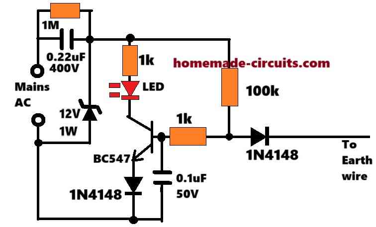
The above circuit could be improved by adding a few more components to it, as shown below:
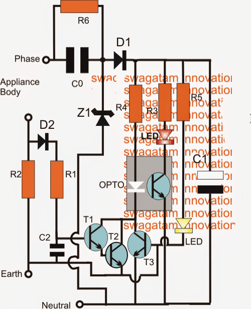
In this circuit we have added a rectifier diode D1 (1N4007) for an improved rectification.
T1 has been enhanced with another BC547 transistor T2 wired as Darlington in order to make the earth leakage detection even more sensitive and allow the use of smaller in-line resistance R2 for better "earthing" experience for the appliances.
C2 (0.22uF) ensures that T1/T2 does not get rattled with unwanted electrical disturbances.
Parts List
R1 = 1K
R2 = see text
R3, R4 = 22k
R5 = 56K
R6 = 1M
Z1 = 15V 1watt zener diode
D1, D2 = 1N4007
C0 = 0.47uF/400V
C1 = 100uF/25V
C2 = 0.22uF
T1, T2, T3 = BC547
C1 = 0.47uF/400V
opto = any standard 4-pin type
Test Set-Up for the above circuits:
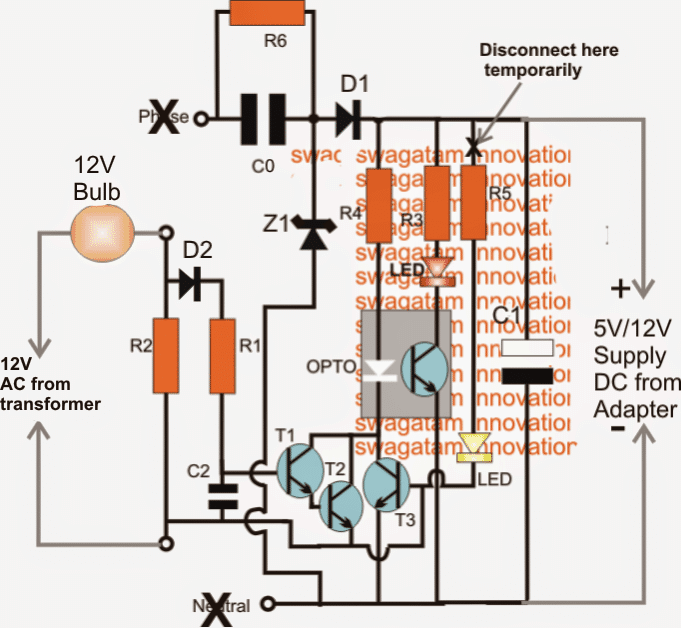
Earth Leakage Indicator
The above diagram shows the test set-up for the proposed earth leakage indicator circuit.
It's conducted in the following manner:
The circuit powered up using an external 12V AC/dC adapter output, remember do not plug-in the circuit to mains while doing this procedure
In the set-up test 12V AC supply is connected across the earth/appliance points via a 12V bulb.
R5 link is kept disconnected for the time being.
The above implementation should instantly switch ON the red LED indicating a current leakage through R2.
Disconnecting the 12V bulb, the red led must also switch OFF, indicating the stoppage of the leakage condition.
Now reduce the 12V bulb load to some lower value, could be done by including another 12V bulb in series to it.
Even with such lower loads, the red LED should be able to indicate the leakages across R2 confirming the proper working of the circuit.
Now removing the above load should instantly switch off the red LED, assuring a correct working of the circuit.
Restore the circuit to its original condition and now it's ready for the actual installation near your MCB.
The functioning of the yellow LEd can be witnessed after the actual installation and connections are done.
If it starts glowing immediately after the installation would indicate a bad or incorrectly wired earthing line.


Questions & Answers
How do you understand which components to choose and how many to choose like you have used 3 transistors I don’t know it how it’s done and then connecting them like how should I connect according to my needs please help I also want to design my own circuits
Designing circuits becomes easier when you first understand the function of each component. For example a transistor can be used as a switch, amplifier, oscillator, current booster, etc. The number of transistors depends on what functions are needed in the circuit.
Normally circuit design starts by defining the required input, output, voltage, current, and control functions. Then suitable stages are added one by one. For instance, you may need one transistor for sensing, another for amplification, and a third for driving a relay or a load.
The best way to learn is to study existing circuits and analyze why each component is used. Then try making small modifications and observe the results. After some practice you will naturally begin to understand how many components are needed and how they should be connected to achieve a specific function. Circuit design is mostly a combination of theory, experience, and experimentation.
Dear sir,
Can you provide a circuit for if the Earth line is disconnected led to be light on for in 230v AC?
Dear Sir,
I have tested it, It’s working as expected. can I improve the LED brightness?
Thank you very much, sir.
That’s great Duminda, thanks for updating…
You can try reducing the 100k to some lower value and check the response, maybe to 68k or 47k…
Dear Sir,
I have implemented the circuit according to your advice, and it is functioning as expected. However, the circuit turns on and off continuously, and the 4148 diode and BC547 transistor frequently burn out. I intend to use this circuit continuously at my home.
Could you please advise on how to resolve this issue?
Thanks for the update Duminda,
The circuit which I provided you above runs on 12V DC, so the BC547 and the diodes can never burn. If your 12v zener diode is fine, then the rest of the circuit components should be also fine and intact, nothing should burn.
Please check the voltage across the zener diode and the circuit, if you find it to be 12V then there’s no way anything should burn in the circuit.
Be careful, the circuit is not isolated from mains AC, and therefore is extremely dangerous to touch..
Dear Sir, I have used this circuit with my power guard circuit power supply. It also includes a 225J 400V capacitor for AC voltage reduction, which is further regulated to 12V using a 12V, 1W Zener diode.
Thank you Duminda,
If it is regulated with a 12V zener and if the zener diode is working fine, then nothing should burn in the circuit.
Please replace the 1N4148 diodes with 1N4007 for increased safety of the diodes.
Hi Duminda, you can try the following circuit:
This will indicate whether the earthing is working good or not…
The circuit is not isolated from mains AC, so be extremely careful while testing this circuit…
I check My whole ckt all Ckt is ok ..and the vtg between T1 and T2 is 12v
I have explained the circuit correctly please read and understand how it works, then you will be able to troubleshoot….12V is wrong, it should be 0.6V between base ofT1 and emitter of T2.
Make the first circuit, and try again.
Hii sir i made these ckt but ..when i start the ckt R2 is start burning and no no led is glows..why this happen please help
Samu, did you make the test set-up using 12V? R2 cannot burn at 12V
No sir i apply 12v supply directly through transform becoz bulb is is not available..is that i doing the right way ..becoz bulb is not available please help
I am sorry, R2 is not 1K, but is supposed to be a small value resistor, and that is why a bulb is required, otherwise it will burn.
For the time being you can use 470 ohms for R2, just to check the LED behavior.
Sir.is change R2 but sir LED is not glow ..
measure voltage across T1 base and T2 emitter, it should be 0.6V minimum….there may be some fault in your circuit that is why no LED is glowing…..
Even if you apply 12V directly to 1K (R2), still it should not burn.
Sir,
How much DC voltage we will get in this circuit after AC rectification?
Can I install 12 volt relay in parallel with LED (R3 circuit) so that it will work as circuit tripper? 🙂
Thank you Sir
S Raja, for a relay you will have to use C0 as 105/400V or 1uF/400V…to get 50 mA out
Dear Sir,
When I stimulate the test circuit in multisim the optocoupler does not get activated ,so the red led does not glow .Why?
Sir, could you post on how to interface force resistor sensor with Arduino and the Arduino program..
Thank you sir
Rahul,
you can reefer to this article or more info
https://www.homemade-circuits.com/2016/05/force-sensing-resistor-explained.html
that's great Sumalya, thanks for updating the info.
Sir,I have solved the problem by decreasing the resistances R3 and R5 and it works fine!!!
Dar Sumalaya, I'll redesign an easier circuit and post it soon…
Hi. I've prepared the circuit but leakage LED never turns off. Where am I missing? Also the capacitor is 100uF or nF? Best regards.
…the electrolytic cap is 100uF, not 100nF
Hi, if the earthing is not good enough it will not be able to ground the T2 base and therefore the red LED will continue to glow.
connect a 3V or 6V zener between the emitter of T2 and the neutral line, and check the response if still it doesn't solve the issue, let me know, I'll try to upadte an easier one
I guess this circuit its not so usefull to any user, since cannot trip the appliance's power,it can only show its status by means of a led.
The most important thing its the RCB (Residual Circuit Breaker)it will certainly cut off the power to your appliance in case of leakage and you can tell from NOT working !
a tripping action may not be mandatory for minor leakages, because small leakages may not be hazardous but might increase the utility bill.
the above circuit in intended to get a visual indication if there's some kind of leakage which is rather common in every house.
Once the user sees this, the issue can be corrected by identifying the cause.
By the way I have an ELCB design which includes a cut-off feature:
https://www.homemade-circuits.com/2011/12/make-simple-earth-leakage-circuit.html
(Continuation of above comment)…….sir, just observed clearly, transistor T3 blew off, it melted and its emitter and collector melted and cut…..
..if you have any issues with the post, feel free to express them under the article.
Thank you SS, you have done a nice job.
Please see the published post here:
https://www.homemade-circuits.com/2014/06/making-helping-third-hand-for-aiding.html
Yes you may send your pic, I'll post it in the article.
And by the way sir, you also asked my picture for posting the article with my name, if i am not wrong….. should I submit it sir………?
Dear sir, please contact me on my mail Id or here if anything is wrong or if any further information is required from my side…….and Thank you once again………….
You are welcome Srinivas,
I'll check it out soon. thanks!
Dear Sir, I have sent all the details to your mail(homemadecircuits@gmail.com). please check them out. And thank you very much for posting the photos sent by me regarding "Self Regulating, Automatic Lead Acid Battery Charger Circuit". Thank you very much Sir……
Regards,
Sai Srinivas.K
Dear Srinivas, thank you very much! I appreciate it, please go ahead!
Dear sir, thank you very much for your support. And sorry for including external links, but there is no other way i could convey the information to you…… . And I will send you all the deteils and photos of th e instrument to your mail id(homemadecircuits@gmail.com) soon maybe within 3-4 days. Thank you very much for your support to me. 🙂
Thanks and best regards,
Sai Srinivas.K.
Thank you dear SS, I appreciate all your efforts, and yes if you can submit the article with all the details, I'll make sure it gets published in my blog with your name and picture.
I would be deleting this conversation shortly since there are a few external website links here.
Dear SS, that's a wise decision, learn all the basics first and come back with confidence.
I appreciate your wise decision.
You are always welcome here….
good luck and best wishes to you!
Thank you for being a part of this blog.
Dear sir, i wanted to do this circuit as our apartment's earth is very weak and it does not absorb any of the leakages….and any leakage in anyone's home shows effect on our appliances and we get a strong shock at that time. so this circuit is to be made in order to help ourselves from not getting shocks….otherwise, i never prefer this type of circuits which are not isolated from mains. But as you are cautioning me this many times for my sake, I prefer quitting than making…..NOw I dont understand how to make an earth leakage indicator circuit to help me and protect us….Anyway, thank you very much for all your help, I disturbed you a lot…..sorry for that…..But I learnt a lot, thank you for that…….have a nice time….bye, I'll be back after 1 year as my summer holidays are over.
By the way, all the circuits that I made from your blog are still working and I installed them in my house like automatic plant watering system, rain sensor, automatic day/night switch, auto wiper switch for car, auto battery charger, low battery and overload cutoff, and many many more(maybe 25-28 circuits). Thank you for all that. You're indeed a good teacher.I never like to miss you, I need your help maybe in future, I'll keep in touch with you, bye for now…..
yours,
sai srinivas.K, with bunch of thanks.
SS I won't recommend this circuit to you because it's for experienced hobbyists only, so please quit, and go for other simpler projects:)
dear sir, here are the links….i think you might understand after seeing these schematics…..
https://drive.google.com/file/d/0B_R45ksolHSmeEQwTFhjV1pvSDA/edit?usp=sharing
https://drive.google.com/file/d/0B_R45ksolHSmeTBpUVJCb080d2M/edit?usp=sharing
SORRY for disturbing you very much….but there is no one except you who helps/can help me…in this regard you are the only one and i feel very very lucky for having a friendly, kind-hearted, helpful man like you….hope you understand…….good day.
Best regards,
ss.
Dear Ss,
you shouldn't have connected it to mains AC unless it was confirmed on the workbench.
The LED should never be ON without any load connected with R2, so it means your circuity wasn't proper right at the start but you still proceeded with it.
If you do it in this way you are going to get even bigger fire hazards:)
so be careful and do exactly as I tell you do.
reassemble the circuit afresh and test it entirely on DC 12 voltage first and then gradually proceed as per my instruction.
This time even for the load across R2 use DC 12V, just for initial confirmation.
I'll also recommend connecting a diode in series with R1, I'll include it in the diagram also shortly.
By the way once again I would like to caution you that this circuit is not for novices, it's for people who are above 18 years and have a reasonable experience of practical electronics and also are well versed with the basics of electronics.
Dear sir, I made the circuit and tested it using the test procedure. But the circuit started ringing buzzer and the led also glew very dim before connecting the 10watt bulb to r2 in series(I.e., when connected the adapter power supply without connecting 10watt bulb). And when I connected the 10watt bulb and switched it on, there is no change in the sound or brightness of buzzer and led…so,I connected 20 watt cfl and r2 blew off. I replaced r2 with 10ohm 1watt resistor and connected the circuit to earth pin and phase and neutral with soldering iron's earth pin as appliance body..when I switched th power on, huge sparks came somewhere between the three transistors. I even cleaned th pcb to avoid possible leakages due to flux after soldering. I am afraid, please, can you help me why this happened, I mqde the second circuit(the 3 transistor one).
Thank you very much sir….
sorry SS, these are not correct, you should do exactly as I have explained in the previous comment……
Dear sir, this is my problem :
1)if any appliance leaks in other houses, the current or leakage comes from EARTH TO APPLIANCE BODIES in our home.
2)but however the current passes through r2 but in REVERSE manner viz., earthing pin to appliance body, in this condition , does circuit detect and indicate, sir?
3)Or if the leakage should come from appliance body, then the earthing wire should be connected to appliance body/bodies nomally and r2 up end should be connected to body/bodies and down end to earth I.e., r2 up and low ends are connected together and connected to earth……
I'll try to draw a example schematic of above explanation so that you can understand easily….. thank you very much my dear sir…….
Regards, ss.
Dear SS, the current will always pass from the appliance to the earthing.
you'll simply need to disconnect the earth wire in the main board where it first links with your house wiring.
Connect this wire to the "earth" point of the circuit and connect the "appliance" point of the circuit to the point where the main earth was previously connected. This will allow all the leakages to pass through R2.
Dear sir, bu the way, I didn't get th e point how to connect the circuit to ground and appliance… is it like this…. appliance earth wire—–r2—-into earth. If it is like tthis, then if I want to get common leakage from all appliances, then I hav to cut th appliances common earth wire and connect it to upper end of r2 and lower end to earth….right sir? But what I wanted to tell you is that I am living in a apartment..and its proved that the geyser is leaking voltage into earth…so when ever they switch it on, we get shock from our appliances as their body is also connected to same earth…….. so I think this circuit doesn't suit for my need bcz I cannot cut the earth wire from homes and keep this in middle of home earth wires and main earth……..so if this circuit should help me, it should sense the voltage from eathing pin and give buzzer thats all…, if I'm right…….if I'm not wrong, I think I should eliminate r2 and connect the r1 to earth pin and remove weak earth sensing part of the circuit,…..maybe…..hope you understand my doubt and find a solution for it……thank you very much sir….
Yours
Ss.
Dear SS, the earth leakage current must pass through R2 otherwise it won't detect anything. You must remove the earth main connection from one of the sockets where it enters first near MCB and connect it with the circuit's "earth"…. next connect the "appliance" point of the circuit to the socket point from where the above earthing wire was disconnected.
Dear sir, thank you for your he) p ill wait until you update the article with testing related guidance……and by the way, I bought a new capacitor today(new stock arrived)….because I cannot trust that old capacitor, it is also damaged a bit as you can see….here's the pic of NEW capacitor…https://drive.google.com/file/d/0B_R45ksolHSmb3o0anVfalpfSVU/edit?usp=sharing …..the size of this is very small, but the retailer told its 400v only……please confirm….thak you and regards….
SS, this circuit will not detect your neighbour's appliance leakages, it will only detect your house appliance leakages
And I forgot onething, the geyser that is leaking is not ours, its our home's beside portion's geyser that is leaking and they never change their geyser or coil……such a brainless people, they even dont know that they too get shock, and they never listen to other's words!!!!! Please help me how to modify this circuit and to make it to help me…..thank you very very very very very very very very very very very very very very much sir……
Ss.
Dear sir, you are right, though I eanted to buy a new one according to your advice, I tested it(bcz retailer told its 400v). I connected led as a load after 10k 1watt resistor and 1n4007 diode, 100mf 25v cap, 15v 1w zener……and after wometime the capacitor BLEW….and immediately, I switched off the mains switch…and all this is done under adult supervision and with safety like goggles, fire extinguisher and circuit is at a distance of 5metres from me bcz I connected the cicuit to mains ising 5mtr extension box….now I understand tht i should follow your advice exactly or face the consequences!!!!!!!!!!…now ill buy a capacitor which has volts print on it….and show it to yo u before using……telling thanks, regards, etc.. doesn't suit you bcz your help is more than what those words could mean…. -SS.
Dear SS, I have updated the diagrams appropriately, please check above and follow them accordingly.
I am not sure if it's 400V rated because the codes are not familiar to me, even I could not find them through online sources, better replace it with a properly indicated capacitor, the voltage print is a must.
Dear sir, thank you very much…..here is the link of th e capacitor….https://drive.google.com/file/d/0B_R45ksolHSmNXJyQzFZcl9nVVU/edit?usp=sharing Also please tell me if I should use DIL(dual-in-line)for soldering the opto sir, or if I should directly solder the opto on strip board. ?..sir, this is the first time im usng a opto…that's why I am getting this doubt…….and here is the pic of new capacitor that I bought today if you tell me which to use, ill proceed……thank you very much….and I assure…."no more doubts and disturbance"….once you reply, I'll be back soon with Pics of circuit…….
Yours,
Ss….with best regards…
Dear Ss, you can include a fuse, but MOV may not be required because the zener diode would take care of the surges. use a 1amp fuse
thank you very much for your invaluable help sir……….
Dear sir, can i use a fuse and mov to protect the circuit from spikes and high current? if i could include a fuse and MOV please help me by suggesting a MOV and the fuse rating….
thank you very much sir……….
regards
ss.
Dear SS, the capacitor is OK, can be used here.
Solder the opto directly on the general purpose board just as we solder an IC or any electronic component, make sure you do not short the pins while soldering.
do it on table first, test it with 12V DC from a 12V adapter.
I'll try to post a diagram of the test set up soon may be.
Dear sir,…first of all very sorry for disturbing you again and again, i wanted to ask you something…..I got the 4n35 opto…and It has six pins, can you help me out and tell me which pins I hav 2 use sir….? And also please see this pic https://docs.google.com/file/d/0B_R45ksolHSmNXJyQzFZcl9nVVU/edit?usp=docslist_api
This is a component which I found in a desktop's cpu power supply 4 years ago….I dont know whether it is a capacitor or not…..but I think its a capacitor thst is specified above…..can you please tell me ig I can use it……
Best regards,
Ss.
Dear SS,
the image is not opening, you'll need to change the sharing option to "public" for enabling that.
for the opto-coupler you can refer the following image:
Dear sir, if I want to connect the unit in common to all appliances, near MCB, should I eliminate r1 and r2 and connect the base of T1 to earth…?…..thank you very much sir…..
dera SS, you'll need to first check and confirm the circuit on table, if everything goes right only then you should go for the final install…
dear sir, i thank you very much for you advice…..i know its quite risky job to open MCB….and i never do it whatsoever the circumstance be…so i asked my parents and they informed an experienced electrician(yesterday) and he would do the job…only soldering would be done by me….
i thank you once again for your valuable advice….
Dear SS, R1, R2 are the heart of the circuit, they are compulsory.
connect the "earth" to main earth of the board and "appliances" to the earth line of the home wiring.
please note: this circuit is not easy and will require an expert's assistance and is also highly risky, not recommended for hobbyists under 18.
Dear sir, thank you for all your help……and a final help is needed regarding the 15v 1 watt zener, which is unavailable in my area….so I wanted to ask you if I could use a 18v or 12v zener in the place of 15v zener(I will use 7815 if I could, pls tell me)…..also the optocoupler is unavailable(today some shops are closed but tomorow I'll check rest of the shops….)but in case they're not available, can you guide me how to make a homemade opto…, if possible…..I cannotysay any thing like thanks….because there is no word in this world with which one could thank your hardest of the hard works…..your hard work really returns you a lot in future……I dont even know how to express my thankfulness…you're great man,….perhaps a man born to help…..and an embodiment for millions in this world!!…..what else can I say for your help…..??
yours,
ss.
Thanks you SS, it's my pleasure!
Opto coupler are easily available in electronic spare parts market, you could use any 4 pin type such as 4n35, the retailer will suggest you if there's an equivalent.
i wish you all the best!
Dear Swagatam, while i have not yet build this. But on my appliance The Freezer and CPU Computer, got sum of about 100v at Ac voltmeter, may T1 handle it ?.
There is no rectifier diode, is it not dangerous for c2 and D1 while negative current would flow at 0.6V on D1 forward bias.
Kindly, help me understanding for these. Thank you very much.
Best Regards. Gani in Batam.
Dear Gani,
The transistor is no connection with the load, it's positioned only for sensing the volatge across R2.
The zener diode passes the psotive 12V and grounds all that's negative so it behaves like a rectifier diode also, but you may include a 1N4007 diode if you feel so.
the diode should be in between the circuit positive line and C1, and the zener across the junction of C1/rectifier diode and ground