In this article I have explained a customized water flow controller circuit with timer.he idea was requested by Mr. Daljeet Singh Sokhey.
Technical Specifications
Right now I am working on a different project and would like your help. There are 2 inputs and both must remain high for a period of 30 seconds for the one single output to go high (AND switch)
If either one fails, the timer should also stop and reset and then start again when both inputs are high again.This is basically to check for the availability of water flowing thru a pipe.
I am using a solenoid valve to control the switching on and off of the water and a flow switch to confirm that the water is flowing.
This switch AND the solenoid must remain continuously on for 30 seconds to confirm that the water is flowing properly. And if this condition is satisfied it should give a high output that can be used to trigger other operations.
You can name it whatever you like, something like Water Flow Confirmation Circuit or anything.The timer will keep only the solenoid ON.
The flow switch turning ON is dependent on the solenoid allowing the water to flow successfully.
That will result in the voltage going high from the flow switch. and this high voltage from flow switch must be sustained for as long as the solenoid is ON(30 seconds). if during that time period, the voltage from the flow switch drops to LOW, the timer should reset which would switch off the solenoid.
Maybe we can add here another timer circuit which will make it retry after, say, 3 minutes or so (adjustable).
And once the solenoid and the flow switch have remained on for 30 seconds, it should give a high output which can be coupled to a relay to switch on some other circuit.
The solenoid needs to be switched off afer 30 seconds. Solenoid and the switch are both 12 V dc
The Design
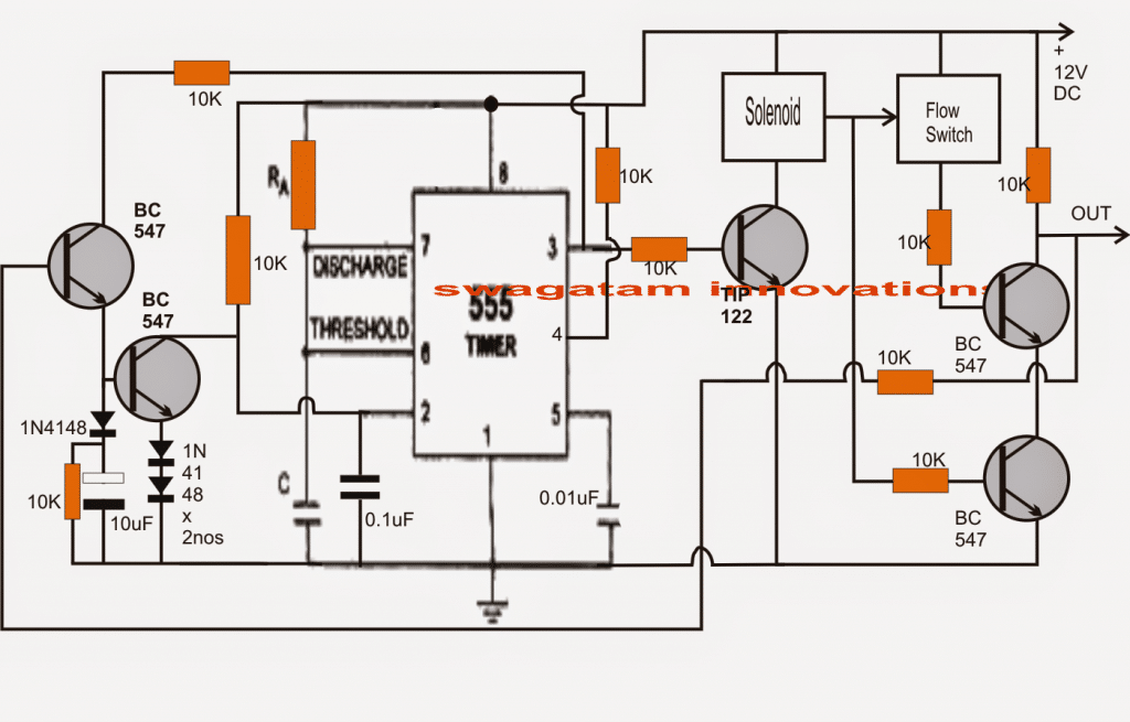
In the proposed water flow controller circuit, the IC 555 is configured as the 30 second timer through its monostable mode.
When power is switched ON, the 0.1uF capacitor at pin#2 of the IC provides a momentary logic zero to this pin triggering the IC output high, the IC starts counting as soon as this takes place.
The above high delivered at pin#3 of the IC actuates the transistor and the connected solenoid.
The solenoid opens the gate for the water to flow, which is detected by the flow switch and its switch ON too.
The above operations presumably happen too quickly and a relatively simultaneous positive triggers from the two devices reach the bases of the two NPN transistors which are arranged to form a "NAND" gate.
With both the transistors switched ON, we have a zero logic across the collector of the upper transistor, indicating the correct state of the circuit and both the devices functioning correctly.
In the meantime the IC counts for 30 seconds, after which its pin#3 reverts to a low switching OFF both the devices which obviously renders a high across the shown OUT terminal of the circuit providing the intended "30 second lapsed" signal to the following stage in the system.
In case any of the devices malfunction, the respective NAND transistor is deprived of its base trigger triggering a high at the output.
Under the above condition the upper transistor at the extreme left receives a base trigger from the OUT terminal of the circuit and it switches ON, however since the IC 555 is sill counting with its pin#3 high allows the voltage from pin#3 to pass via this transistor to the base of the lower transistor which after a certain delay resets and restarts the 555 IC operations by grounding its pin#2.
The operation then repeats.
The delay can be altered by tweaking the value of the 10uF capacitor.
Circuit Diagram
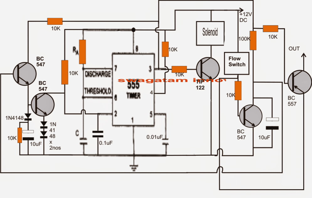
As per the corrective suggestions the above circuit is modified as shown below, please refer to the comments for the details:

Comments
Hi Swagatam, I need to know if ic 4040 can be cascaded. The first one will get the clock frequency from the ac line (60 Hz) and convert it into 1 pulse per minute (1 ppm) thru AND gate ic. This same pulse will be used to reset it. Can this same pulse be used to clock another 4040 to produce 1ppday and that connected to another one to produce 1pp7days. Is it feasible
OK understood,
You can send it to my email
hitman2008@live.in
The AND gate is used since I am using the first 4040 to divide the 60Hz signal by 3600 to get 1ppm. so at the count of 3600 its outputs5,10,11,12 will be high and by ANDing them together, I will get one pulse. This is the one that will be used to clock the next 4040 and also to reset the first one. and so forth for the next 4040. I was trying to upload the schematic on imageshack.com but I think you cant upload a pdf file there. Is there any other way I could email you the schematic to check it out. Thanks
Hi Daljeet, yes 4040 ICs can be cascaded for getting very long delays, but i did not understand the role of the AND gate.
Thanks, now waiting for the description of the circuit
will try to update it soon.
Hi Swagatam, Sorry for replying so late. In fact I did not get the email notifying me of your reply. But anyway, Yes what you have stated above is correct. The output should go high only and only if the flow switch has detected the flow of water for 30 seconds. Otherwise it should keep resetting with zero voltage at output. I am also trying to figure a way out and I will post it to you as well but lets hear from you first.
OK I'll try to modify the diagram accordingly and post it soon.
Hi Swagatam, Thanks for this post. A couple of concerns.
1.The lower BC 547 Tr on the right hand side needs to be connected to the Emitter of TIP 122 before a 10K resistor. This will turn on the transistor when the current flows thru the coil of the solenoid.There is no electrical connection between the solenoid and the flow switch as indicated by the arrow in the drawing.
2. The output cannot go high if any of the two malfunction. Basically there can be only one scenario and that is that the flow switch does not detect the flow of water and remains open after the solenoid has been switched on. In any other case, if the solenoid does not operate, the flow switch will NOT operate. However as per your description, if any of them fails, the output will go high. That would defeat the purpose of the whole circuit. This high output is going to trigger another circuit which it should not if the flow switch remains off OR goes off during the 30 second time period.
Let me know what you think of that.
Thanks
Hi Daljeet,
Simply put, the output should go high only after the 30 seconds time has lapsed and the flow switch has functioned as expected from it during this period of time…..for any other malfunction may it be the solenoid not operating and/or the flow switch malfunctioning will result in a zero voltage at the output.
The circuit will consider the flow switch output malfunction and will keep resetting the IC until the flow switch becomes operative.
Please confirm the above then I'll do the required corrections.