In this post I have explained how to convert smps into a solar charger circuit. The method will result in an extremely efficient and fast solar charging of the connected battery.
SMPS Solar Chargers
SMPSs have become very common nowadays and we find them being used in the form of AC to DC adapters wherever needed. The best example is our cell phone chargers which are actually compact SMPS 5V chargers.
Solar charger devices are also becoming popular nowadays and folks are constantly in look out for options in the form of solar chargers having the most efficient charging response.
Solar panels or PV devices are normally utilized for charging lead acid batteries which tends to take relatively long hours for getting fully charged, besides when the sunlight conditions are bad things start getting even more sluggish.
For tackling the above condition or rather for enabling quicker charging from solar panels, special MPPT based soar chargers have been developed which effectively monitor the solar panel maximum power point levels and generate the most efficient charging conditions for the connected battery.
In this article although we won't be discussing an ideal MPPT, yet the discussed method will give you an opportunity to acquire the most efficient way of charging your battery through a solar panel.
As proposed in one of my previous articles discussing understanding solar mppt solar chargers, a switch mode based power supply (SMPS) is probably the best option for making it work as a solar charger circuit, so here I have explained how to make an smps based solar charger circuit at home.
Making an SMPS can be quite complex and might require considerable amount of time and knowledge for the implementations, so here rather we will focus on how to convert a ready made smps into an effective solar charger circuit quickly.
For this you will require the following materials, assuming the battery to be charged is 12V rated:
A ready-made 120V or 220V to 12V SMPS unit having current rating equal to 1/5th of the battery AH which is to be charged.
A few Solar Panels whose total open circuit voltage equals around 100V.
Connecting wires.
Converting SMPS into a Solar Charger Circuit.
As we all know a normal mains SMPS are mostly rated with minimum of 85V to 100V input in order to provide the specified output DC, let's assume it to be 12V, meaning for acquiring 12V it must be supplied with a minimum of 100V at the input.
Keeping the above issue in mind, we must select a solar panel which may be able to produce approximately 100V for making the procured SMPS work.
Since PV panels with such high voltage might not be available, we may opt for many low voltage solar panels connected in series for generating the above voltage.
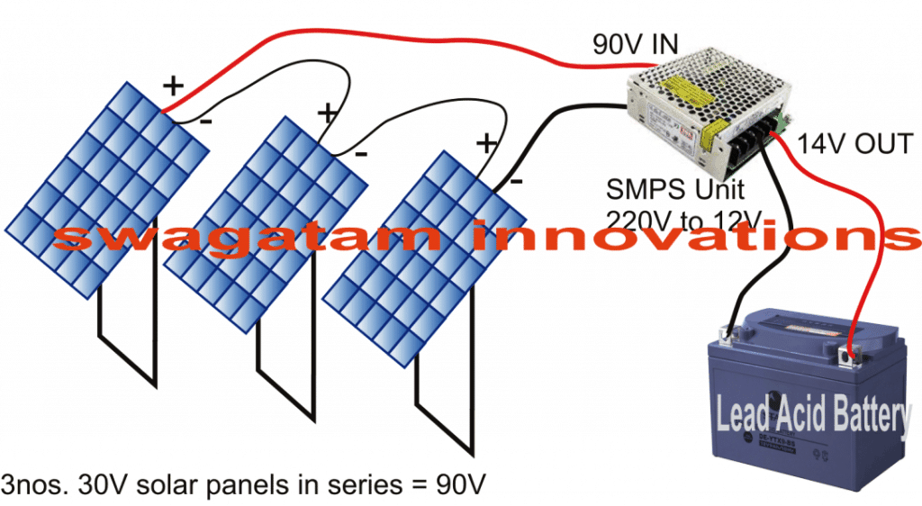
For instance you can go for 3nos. of 30V solar panels and connect them in series to get 90V from it, which might just do the job.
The above input supplied to the procured SMPS would generate the required 12V which may be directly attached to the battery for charging it efficiently.
However a 12V supply might not be enough to charge a 12V battery, we would need at least 14V for it, but that's not a big issue. You will find that most SMPS units have a small voltage adjustment preset situated just beside its connector, which can be appropriately adjusted to raise the 12V to 14V.
However, if you don't get an SMPS with this adjustment preset, you can very well open it and adjust the output voltage with some modifications. The procedures can be learned in this article which explains how to modify an SMPS circuit.
That's it, you have just now converted a ready made SMPS unit into an efficient solar charger circuit that might generate results equivalent to MPPT charger circuits for you.
Main Advantages
The key advantages of this SMPS concept is its compact configuration and a 90% efficiency enabling high current battery to get charged optimally and quickly.
For example we can use an SMPS rated to generate 20 amps, then we can charge a lead acid battery having an Ah rating of as high as 200 Ah, and if the battery is Li-Ion type then it can be as powerful as 40 Ah Li-ion battery.

Comments
dear sir i have 110v solar module with 0.98amps currents need to do battery charge with solar pannels so please guide me to build the circuit for this. and please if possible can you send me the details to my mail id pradgb@gmail.com