A simple cell phone charger with timer circuit is presented in the following article, which could be used for charging a given Mobile phone for a specified predetermined length of time. The idea was requested by Mr. Saad.
Circuit Objectives and Requirements
- Could you design me this charger circuit ? Input 230V 60 Hz, and the output 3 USB port for charging Smartphones.
- What I need in this circuit is a Timer (Three sets of time), 30 mins, 60 mins and 120 mins.
- So I connect my phone to any of the three usb port and press (on/off) switch then the time start for example 60 mins then the power cut off.
- Hope you understand my request.
Circuit Diagram
Circuit Operation
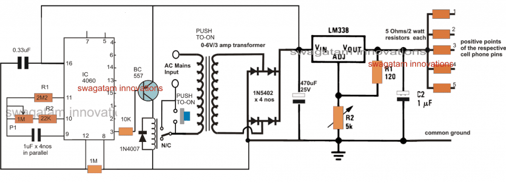
The proposed cellphone charger circuit with timer can be seen in the above figure, the design primarily comprises of an IC 4060 timer stage and a DC to DC multi cell phone charger stage.
The cell phone charger section is a standard LM338 based charger circuit, wherein the output is bifurcated into 5 individual charging outputs facilitating charging 5nos individual cellphones. From these outputs 3 channels could be utilized for the intended 3 cell phone charging, at a rate of 1500mAH each. The series resistors may be accordingly calculated using Ohms law, as given below
R = V/I = 5/1.5 = 3.33 ohms, 10 watts each
R2 in the LM338 circuit must be appropriately adjusted to achieve around 5V across the output terminals or across C2 terminals.
The timer stage is made up of the IC 4060 whose pinouts are also configured in its standard timer/counter mode.
P1 may be adjusted to get a delay time of around 120 minutes on pin#3, which would allow pin#2 to produce a delay of 60 minutes, and pin#1 a delay of 30 minutes.
Initially when power is applied across the indicated mains input terminals, the cellphone charger circuit with timer does not respond and stays deactivated.
However, the moment the given push button is pressed, causes the N/O side of the relay to get connected with the other unconnected mains wire.
This momentarily connects the AC mains with the transformer leads, which in turn powers the rectifier stage enabling a momentary DC supply input for the IC 4060 timer stage.
This momentary supply to the IC 4060 stage activates the counting of the timer, and simultaneously produces an initial zero potential at the base of the relay driver BC557 transistor, switching ON the relay from N/C to N./O points.
As soon as this happens, the relay contacts now take-over the push-to-ON switch connections and allows the AC to flow through these contacts into the transformer primary.
This ensures that, now even if the push button is released, the circuit is able to get latched into the powered position enabling the LM338 to begin charging the attached cell phones and the timer IC 4060 to count the stipulated amount of time via the pot P1.
As soon as the counting of the IC 4060 gets elapsed, pin#3 (pin#1/2 whichever is selected) turns high, switching of the BC557 and the reverting relay contacts from N/O to N/C.
This action instantly switches OFF and disconnects the mains AC from the transformer, deactivating the whole process and bringing the whole system into its original standby position.
This cellphone charger timer circuit could be yet again initiated simply by pressing the push button for the next charging cycle.
Time Delay for the IC 4060 can be calculated using the formula:
f(osc) = 1 / 2.3 x Rt x Ct
where Rt = R2 +P1 (in Ohms)
Ct = C1 (in Farads)
Parts List
Resistors, All 1/4 watt 5%
2M2 = 1
22K - 1
10K = 1
1M = 1
120 ohms = 1
1M pot= 1
5K pot = 1
Capacitors
1uF/50V non-polar = 4
0.33uF = 1
470uF/25V = 1
1uF/25V electrolytic = 1
Diodes, 1N4007 = 5
Transistor, BC557 = 1
IC, LM338 = 1
Relay,12V/400 ohm = 1
Push button = 1
Transformer = 0-12V/5 amp
Output resistors as per the given formula

Comments
thanx .hope u don’t mind me asking for electronic circuits because you are such a BIG HELP . i’m just starting to hook in electronics.till next request.god bless.
hi swag,thanx for reply,what i mean was simple wifi signal booster antenna for cellphone or laptop using usb cable.
Hi Dennis, it may be any related item but still it will require a lot of accuracy and calculations to build it…
by the way I have seen that whenever I sit beside my wifi 4G device it becomes faster…it seems my body acts a like an antenna.
and can you help me design a signal booster circuit for laptop and cellphone to boost internet and wifi.thanx
sorry, I do not have this kind of circuit with me at the moment, and moreover designing such circuits can be really complex…
hi swag.thanx for fast response.i just opened my email now since my last message to you. can you help me decide what is the best soldering iron wattage and soldering lead diameter to use
in pcb’s.thanx
Hi Dennis, I prefer the following type of soldering iron, It is a 25 watt soldering iron which is normally recommended for most sensitive and normal PCB soldering work
http://www.dnatechindia.com/image/cache/catalog/Soldron_25Watt_1-500×500.jpg
gud day swagatam.can u help me provide:
1. a circuit for rechargeable battery operated soldering iron like ISOTIP with adjustable current to vary wattage from 30w to 60w with digital wattage display using 4.2v lithiun or 3.7v 18650 if possible.
2.circuit for adjustable current to vary wattage soldering iron with digital watts display directly on 220 v. thanx
Good day Dennis, you can accomplish it with a simple IC 555 PW circuit as shown below:
https://www.homemade-circuits.com/2012/05/make-this-pwm-based-dc-motor-speed.html
you can replace the motor with your soldering.
I do not have a digital watt meter circuit at the moment, however you can use a digital ammeter which will allow you to get reading equivalent to watts…you can calibrate the meter range into watts…so basically it will show amps but the modified calibration will enable it to convert the readings into watts…as per my assumption.
how to calculate the resistor and capacitor values for 4hours
please provide me the formula
what is your battery AH rating??
Nice post
Great! Thank You.
Thank you Sir. Would you please provide me with the part list!
Hi Saad, I'll try to update the info soon…
Ok. Thanks for the help.
Would you please add it for me.
Sorry for bothering you.
Saad, you will have to practically check and identify which pinout of IC 4060 gives the required pulses equivalent to seconds or minutes…but before that you will need to build the 4033 counter circuit successfully….
Sir, Thank you for the design.
Can you add LCD screen showing a Digital countdown of a certain time!
You are welcome Saad,
You can add the following design for counting the pulses from one of the outputs of the IC 4060 which may be corresponding to seconds or minutes
https://www.homemade-circuits.com/2013/11/cascading-ic-4033-in-multiple-digit.html