• Skip to main content
  • Skip to primary sidebar

Homemade Circuit Projects

Need circuit help? Post them in the comments! I've answered over 50,000!

Blog | Categories | About | Contact | Calculators-online
You are here: Home / Electronics Theory / Calculating Filter Capacitor for Smoothing Ripple

DIY Circuits | Learn Basics | Arduino Coding


Calculating Filter Capacitor for Smoothing Ripple

Last Updated on July 13, 2024 by Swagatam 57 Comments

In the previous article I explained about ripple factor in power supply circuits, here we continue and evaluate the formula for calculating ripple current, and consequently the filter capacitor value for eliminating the ripple content in the DC output.

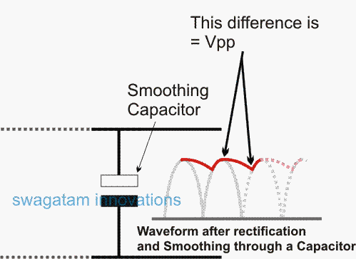
The previous post explained how a DC content after rectification may carry the maximum possible  amount of ripple voltage, and how it may be reduced significantly by using a smoothing capacitor.

Although the final ripple content which is the difference between the peak value and the minimum value of the smoothed DC, never seem to eliminate completely, and directly relies on the load current.

In other words if the load is relatively higher, the capacitor begins losing its ability to compensate or correct the ripple factor.

Standard Formula for Calculating Filter Capacitor

In the following section we will try to evaluate the formula for calculating filter capacitor in power supply circuits for ensuring minimum ripple at the output (depending on the connected load current spec).

C = I / (2 x f x Vpp)

where I = load current

f = input frequency of AC

Vpp = the minimum ripple (the peak to peak voltage after smoothing) that may be allowable or OK for the user, because practically it's never feasible to make this zero, as that would demand an unworkable, non-viable monstrous capacitor value, probably not feasible for anybody to implement.

waveform after rectification

Let's try to understand the relation between load current, ripple and the optimal capacitor value from the following evaluation.

Relation Between Load Current, Ripple, and Capacitor Value

In the mentioned formula we can see that the ripple and the capacitance are inversely proportional, meaning if the ripple needs to be minimum, the capacitor value needs to increase and vice versa.

Suppose we agree to a Vpp value that's, say 1V, to be present in the final DC content after smoothing, then the capacitor value may be calculated as shown below:

Example:

C = I / 2 x f x Vpp (assuming f = 100Hz and load current requirement as 2amp))

Vpp should be ideally always a one because expecting lower values can demand huge unpracticable capacitors values, so "1" Vpp can be taken as a reasonable value.

Solving the above Formula we get:

C = I / (2 x f x Vpp)

= 2 / (2 x 100 x 1) = 2 / 200

= 0.01 Farads or 10,000uF (1Farad = 1000000 uF)

Thus, the above formula clearly shows how the required filter capacitor may be calculated with respect to the load current and the minimum allowable ripple current in the DC component.

By referring to the above solved example, one may try varying the load current, and/or the allowable ripple current and easily evaluate the filter capacitor value accordingly for ensuring an optimal or the intended smoothing of the rectified DC in a given power supply circuit.

You'll also like:

  • cascadingIC4033circuitHow to Cascade IC 4033 in Multiple Digit Counter Display
  • LM567 application circuitLM567 IC Calculator Tool
  • inductor imageInductor Working and Designing, with Formulas
  • How to Understand IC 4017 Pinouts

Filed Under: Electronics Theory Tagged With: Calculating, Capacitor, Filter, Ripple, Smoothing

About Swagatam

I am an electronics engineer and doing practical hands-on work from more than 15 years now. Building real circuits, testing them and also making PCB layouts by myself. I really love doing all these things like inventing something new, designing electronics and also helping other people like hobby guys who want to make their own cool circuits at home.

And that is the main reason why I started this website homemade-circuits.com, to share different types of circuit ideas..

If you are having any kind of doubt or question related to circuits then just write down your question in the comment box below, I am like always checking, so I guarantee I will reply you for sure!

Previous Post: « Digital Power Meter for Reading Home Wattage Consumption
Next Post: What’s Ripple Current in Power Supplies »

Reader Interactions

Comments

Raveesh H P says:
November 29, 2015 at 11:46 am

Dear Sir,

For SMPS (step down) out put capacitor calculation whether we have to take switching frequency as "f" in the formula? please clarify

Reply
Swagatam says:
November 30, 2015 at 6:15 am

Dear Raveesh, in SMPS, the waveform is rectangle or square and also the duty cycle factor is present…so may be the "F" could be differently expressed here in terms of duty cycle %….not much sure about it right now…

Reply
VIJAY AJ says:
November 28, 2015 at 12:44 pm

Sir, I have seen more number of inverter circuits on your site. Can u suggest the circuit which should produce an exact sinewave as same grid supply.

Reply
Swagatam says:
November 30, 2015 at 3:57 am

Vijay, trying to acquire an analogue sinewave replication can make an inverter inefficient, that's why all inverers rely on PWM which is much suited with digital inverters and are able to deliver max efficiency… and also a waveform quite similar to a pure sine wave.

Reply
VIJAY AJ says:
November 27, 2015 at 5:04 pm

Nice post sir really useful information.

Reply
Alamgir Hossain says:
November 29, 2015 at 5:33 am

nice post sir.really helpful….. thanks sir

Reply
Swagatam says:
November 28, 2015 at 6:18 am

thanks Vijay, I am glad you liked it….

Reply
Back to Newest

Need Help? Please Leave a Comment! We value your input—Kindly keep it relevant to the above topic! Cancel reply

Your email address will not be published. Required fields are marked *

Primary Sidebar

circuit simulator image


Subscribe to get New Circuits in your Email


Categories

  • Arduino Projects (93)
  • Audio and Amplifier Projects (133)
  • Automation Projects (17)
  • Automobile Electronics (101)
  • Battery Charger Circuits (85)
  • Datasheets and Components (109)
  • Electronics Theory (149)
  • Energy from Magnets (27)
  • Games and Sports Projects (11)
  • Grid and 3-Phase (20)
  • Health related Projects (27)
  • Home Electrical Circuits (13)
  • Indicator Circuits (16)
  • Inverter Circuits (95)
  • Lamps and Lights (159)
  • Meters and Testers (71)
  • Mini Projects (28)
  • Motor Controller (68)
  • Oscillator Circuits (28)
  • Pets and Pests (15)
  • Power Supply Circuits (91)
  • Remote Control Circuits (50)
  • Renewable Energy (12)
  • Security and Alarm (64)
  • Sensors and Detectors (106)
  • SMPS and Converters (34)
  • Solar Controller Circuits (60)
  • Temperature Controllers (43)
  • Timer and Delay Relay (49)
  • Voltage Control and Protection (42)
  • Water Controller (36)
  • Wireless Circuits (30)


Other Links

  • Privacy Policy
  • Cookie Policy
  • Disclaimer
  • Copyright
  • Videos
  • Sitemap


People also Search

555 Circuits | 741 Circuits | LM324 Circuits | LM338 Circuits | 4017 Circuits | Ultrasonic Projects | SMPS Projects | Christmas Projects | MOSFETs | Radio Circuits | Laser Circuits | PIR Projects |

Social Profiles

  • Twitter
  • YouTube
  • Instagram
  • Pinterest
  • My Facebook-Page
  • Stack Exchange
  • Linkedin


Recent Comments

  • Swagatam on Arduino 2-Step Programmable Timer Circuit
  • Swagatam on Simple Buck-Boost Converter Circuits Explained
  • Swagatam on IC IR2111 H-Bridge MOSFET, IGBT Driver IC: Full Datasheet, Circuit Diagram
  • Swagatam on Electronic Circuit Projects, Tutorials, and Practical Engineering Solutions
  • Kadir on Simple 3 Phase Inverter Circuit

© 2026 · Swagatam Innovations