
In bipolar junction transistors the factor that determines the sensitivity level of the device to base current, and the amplification level at its collector is called beta or the hFE. This also determines the gain of the device. In other words, if the BJT uses relatively higher current to switch its collector load optimally then […]
Newly Updated Circuit Projects:
Voltage-Divider Bias in BJT Circuits – More Stability without beta Factor
Biasing the terminals of a bipolar transistor using a calculated resistive divider network for ensuring an optimal performance and switching response is called voltage divider biasing. In the previous bias designs that I have explained the bias current ICQ and voltage VCEQ were a function of the current gain (β) of the BJT. But, as we […]
Darlington Transistor Calculations
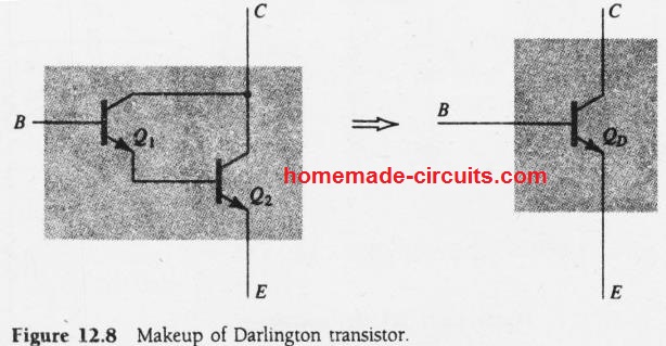
Darlington transistor is a well known and popular connection using a pair of bipolar transistor junction transistor (BJT), designed for operating like an unified “superbeta” transistor. The following diagram shows the details of the connection. Definition A Darlington transistor can be defined as a connection between two BJTs that allows them to form a single […]
Difference Between Op amp and Comparator
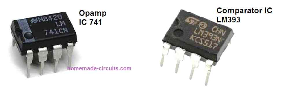
In this article I have explained the main differences between op amp and comparator, and try to understand why op amps are not ideally suited to be used like compartaors. We also learn the main advantages of using compartaor ICs in comparator applications. Basically, you will find many electronic lectures or publications talking about using […]
How to Calculate Capacitors in Series and Parallel
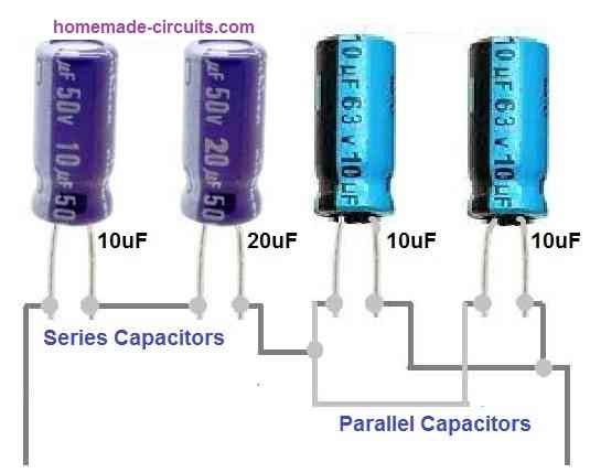
Capacitors connected in series or parallel are very common in electronic circuits. This is done in order to achieve the desired capacitance value and also to make the performance of the circuit accurate. In the following post I have explained how to connect capacitors in series and parallel: Connecting Capacitors in Series When we connect […]
LM567 IC Calculator Tool
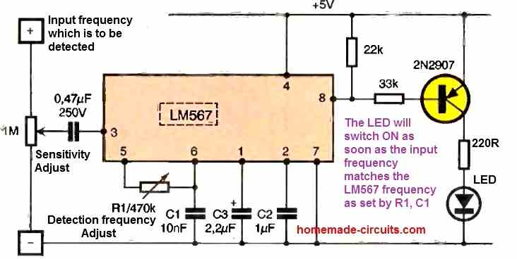
We can use this small LM567 calculator tool for finding the right frequency, Rt, and Ct values for our tone decoder circuit. Now we know that this IC works on one simple relation which is, f = 1 / (1.1 × Rt × Ct) So we can see that this frequency depends only on the […]