Despite its simplicity, the Battery Low Voltage Alarm circuit has a very important function. It forewarns you of approaching battery failure so that you may run to the store and get replacement cells before your equipment stops functioning entirely.
Because of its compact size and low current need, it may be integrated into the devices whose voltage has to be checked.
The project's loud piezo buzzer will then blare to alert you that the battery has effectively run out when the voltage of the battery starts to drop near the end of its life.
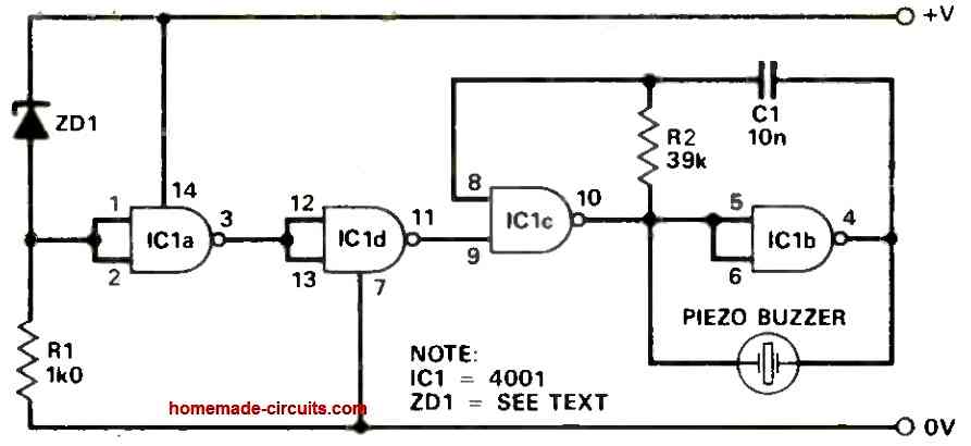
The following schematic of the proposed low battery alarm circuit is quite straightforward. Only one CMOS integrated circuit and a small number of readily available parts are used.
How the Circuit Works
The zener diode ZD1 and resistor R1 work together to create the voltage reference.
You should be aware that the resistor and diode are connected to the negative power rail while the zener diode is linked to the positive power rail, in contrast to how zener diodes are often used, for example, in power supplies.
All of this simply implies that the zener's internal reference voltage is always more positive than the voltage across the resistor.
As a result, as opposed to being fixed with respect to ground (as it would be in the more traditional way of using zener diodes), the voltage supplied to the input of gate IC1a is fixed with respect to positive supply voltage.
In actuality, the gate input voltage increases or decreases in a fixed manner when the supply voltage changes.
The switching-point at which the gate transitions from a high to a low state is crossed as a result of variations in the gate input voltage caused by shifting power supply voltage.
As the supply voltage starts dropping, the gate switches as a result. A variety of frequently used zener voltages are included in Table 1, along with an approximation of the power supply's switch point voltage.
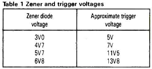
Use a 5V6 zener diode, then, if you want the project to sound the alarm when the power supply voltage drops to about 11.5V.
Use a 4V7 zener diode if the alarm is to turn ON when the voltage has dropped to about 7V.
You might need to experiment because all voltages rely on particular parts (zener diode and gate switching voltages are both slightly changeable).
The low voltage trigger is made up of gates IC1d and c.
The gates IC1c & b, together with any related parts, comprise the core of the gated astable multivibrator. The astable multivibrator drives the piezo buzzer in the opposite direction.
Therefore, the buzzer is silenced when the power supply voltage is higher than the voltage that causes the zener diode voltage to be higher than the first gate's switching point.
The buzzer, however, activates when the power supply voltage decreases, bringing the input voltage of the first gate below its switching point.
How to test this Low Battery Alarm Circuit
You need a power supply with a constantly adjusting output voltage and a voltmeter that can read the voltage range that the power supply covers in order to ensure that your project is operating properly.
To monitor the output voltage, attach the voltmeter to the power source.
If you want the project to sound its alarm, set the power supply output to a voltage greater than that.
Therefore, adjust the power supply to roughly 10V if you intended your project to produce sound when the voltage drops below, let's say, 7V.
Hookup the device to the power source at this point.
Absolutely nothing ought to happen if the zener diode you choose is the right one.
As you gradually reduce the output voltage of the power source, keep an eye on the voltmeter's reading.
The piezo buzzer should beep at a lower voltage, showing that the gadget is functional.
The buzzer starts to sound at voltages below this threshold and stops at voltages above it.
The voltage threshold at which the piezo buzzer sounds will correspond to your chosen voltage if the selection of zener diode is successful.
Using 555 Alarm to Detect and Alert Battery Low Voltage
Originally, this 555 circuit was employed alongside an automatic mains/battery DC power source for transceiver operations.
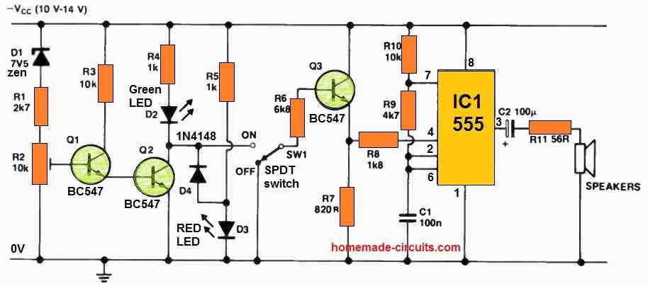
Its purpose was to detect a reduction in DC voltage, with the mains supply typically at 13.6 V and the battery at 12 V, and provide both visual and alarm alerts for voltage drops.
This circuit is well-suited for various applications that require the detection of a decline in the standard DC power supply voltage, offering the added benefit of an audible warning.
This feature proves particularly advantageous in vehicles, where a visual indicator might be easily overlooked.
The stable voltage reference is established by D1, R1, and R2, and the preset R2 is calibrated to ensure that D2 remains illuminated under normal circumstances. Consequently, D4 remains forward-biased, keeping D3 in the off state.
When the input supply triggers a voltage drop across Q2, it causes D3 to switch off, and Q3 is subsequently activated through the action of SW1.
This shift in voltage at pin 4 (reset) of the 555 timer renders it positive, enabling the 555 timer, which is configured as an astable oscillator. The frequency of this oscillation can be adjusted using R9.
To deactivate the audio alarm function, SW1 can be activated, cutting off the flow to Q3. Nevertheless, D3 will continue to provide a visual indication.


Comments
Hi
I, after a bit of trial and mostly error I got the low voltage alarm with 555 timer to work successfully. Only thing is the alarm activates around 8.3 volts. What do I need to adjust to get it to sound at 12.1v. I need to protect my 100 amp hour gel battery.
I’ve checked the voltage divider resistors and zenner diode. All is as expected.
Thanks for your help and website.
Hi, 12.1V is not a low voltage, for a 12V battery. It is not supposed to be higher than 11V according to me.
You will have to adjust the R2 preset for setting up the low voltage trigger for the circuit.
Thank you, Sri Swagatam for the Battery Alarm circuits, ie both ,the one using CD4001 Nand gate as well the NE 555 IC.
For the first, I salute you in craftily using the Zener diode ( non-conventional way) as the ” battery low sensor element”. ) ( definitely ingenious).
The second also has it own special Merit. For many, this is equal to a tutorial. Hats off to you, unconditionally! ( for every other posts as well). ????????
Thank you so much Jay, for your kind words, appreciate it very much.
However, honestly, the above circuit diagrams were contributed by external authors, they are not designed by me.
Anyway, I am glad you found the circuits useful. Please keep up the good work.