In this post I have explained a simple automatic generator choke actuator circuit using a straightforward delay OFF timer circuit and a solenoid device. The circuit was requested by Mr. Bob Perry.
Technical Specifications
I’m in need of a time delay schematic for the following project. I have an electric generator that I can start by means of a control panel from inside my house but need to go outside to close the carburetor choke before starting.
I’ve devised a way of using a 12V car door actuator/solenoid to pull the choke closed but it would be nice to have a circuit that would trigger the solenoid (to pull and hold) for 15sec then stop.
I have a spring that will pull the choke back open after the 20sec has been reached.
The 12V solenoid has to wires and depending on polarity can be used to make it push or pull.
I would like to utilize a push button that I will attach to the control panel to activate the circuit using the 12V battery on the generator, allowing it to energize the solenoid to pull the choke closed.
(Battery Specs: Cycle Use: 14.5-14.9V Standby use: 13.6 -13.8V Initial Current: Less than 6.8A)
The circuit design must not drain the battery when not in use.
I plan on building a circuit board using your schematic and placing it in a waterproof case.
If you can help, I would appreciate it.
Kindest regards,
Bob Perry
The Design
Using only transistors
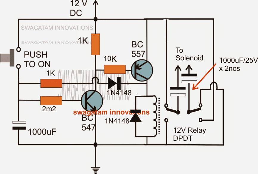
As shown in the first diagram, the NPN/PNP transistor network basically forms a simple delay OFF timer circuit.
It may also be considered a transistorized monostable circuit.
The 2M2 resistor and the 1000uF capacitor determine the length of the delay and thus can be suitably tweaked for the required amount of delay.
Preferably only the capacitor may be altered by trial and error for acquiring the desired timing.
As soon as the momentary push button is pressed, the supply voltage is allowed to enter the base of the BC547 via the 2m2 resistor, also simultaneously results in charging the 1000uF capacitor.
The above operations trigger the NPN/PNP setup along with the connected DPDT relay. The relay activates the solenoid in turn.
The whole operation clicks within a fraction of a second and holds on even after the switch is released.
This keeps the solenoid switched ON until the time elapses through the discharging of the 1000uF capacitor, wherein the relay and the solenoid switch OFF and revert to their original positions.
It must be noted that here a spring load solenoid may not be required as the use of the DPDT relay and its connections effectively reverses the polarities of the solenoid appropriately for the intended actions.
This choke actuator circuit would consume zero current when not in use and connected to the supply.
Circuit Diagram
Using IC 555
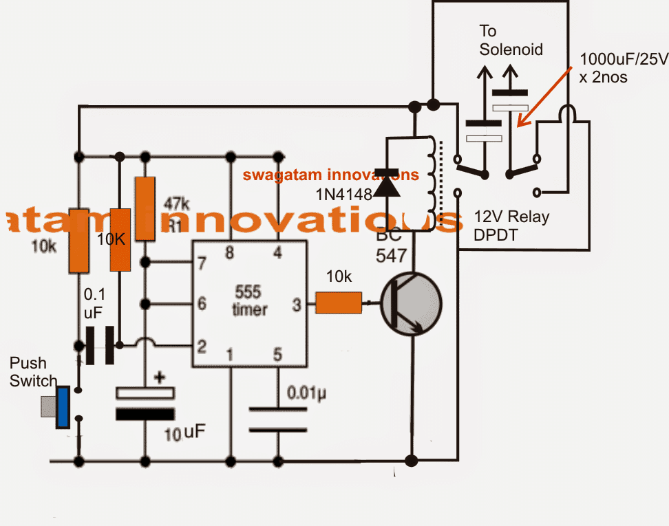
The above circuit can also be made even more accurately by the set up shown below. Here we see the IC 555 being configured in its standard monosable mode.
The push button is used to momentarily ground pin#2 of the IC such that the connected devices across pin#3 of the IC get activated and hold the position even after the switch is released and until the set time elapses as determined by the values of the resistor/capacior across the pin#6/7 of the IC.
This automatic generator choke actuator circuit would consume around 5mA when it's in a non-operative state.
Feedback from Mr. Bob
Hi Swag,
Thank you for your time and the schematic. People such as yourself, make the internet a valuable resource.
Just a couple of questions:
1) Can the 2.2Meg resistor be replaced with a trimmer pot to vary the time or should I only vary
the two 1000uf caps only?
2) Do I connect the positive ends of both capacitors to the positive lead of solenoid and negative
lead of solenoid to ground?
Thanks again,
Bob Perry
Solving the Circuit Query
It's a Pleasure Bob!
1) Yes the 2.2m resistor can be replaced with a preset, the value is not critical you can even try a 1M preset and simultaneously try experimenting with 1000uF cap which is connected with the 2.2M resistor (it's a single capacitor). Both values together (2.2M and 1000uF) or individually can be tweaked for getting the desired delay.
Make sure you add a 10k resistor in series with the preset (transistor base) to safeguard the transistor.
2) You can either connect the positives of the capacitors "towards" the solenoid or the negatives "towards" the solenoid, no other combination should be tried, basically we are trying to implement a non-polar capacitor here...therefore alternatively you can procure a non-polar 500uF/25V capacitor and connect it in series with any one wire of the solenoid anyway round.
The solenoid wire connections (polarity) becomes crucial only with the relay contacts once the above cap assembly is done, the above cap assembly becomes a part of the solenoid.
The slenoid wire polarity can be confirmed simply by operating the mechanism, if it moves oppositely... just swap the wire across.
Best Regards.
Comments
Hi, this was what I asked in the comment section of ATS which you said you had no idea of. How will you connect it?
Hi, I do not have any idea about generator chokes, I have only drawn a timer circuit as per the description in the request.
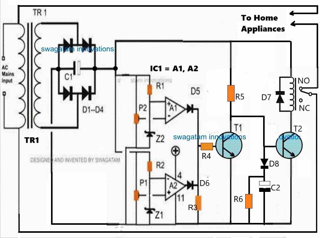
For complete automatic generator starter with changeover, you can investigate the following design:
2 Simple Automatic Transfer Switch (ATS) Circuits