In this post I will show how to construct a digital clock using RTC or Real Time Clock module. We will understand what “RTC” module is, how to interface with Arduino and what it does.
By:
RTC module is a circuit, which keeps track of current time accurately. It does two functions, it communicates with microcontrollers and microprocessors to give current time and act as backup circuit for maintaining time in case of power failure, since it has build-in battery backup system.
We can find RTC in any electronic devices where time is an important function of the gadget.
For instance, our computer or laptop maintains its time even after power is plugged off or battery is removed. On the motherboard of any computer we can find a CMOS battery, which powers the RTC circuit.
Similar kind of circuit we are going to use in this project.
RTC module is an inexpensive device which can be found on any E-commerce sites and your local electronic project shops.
Illustration of typical RTC module DS1307:
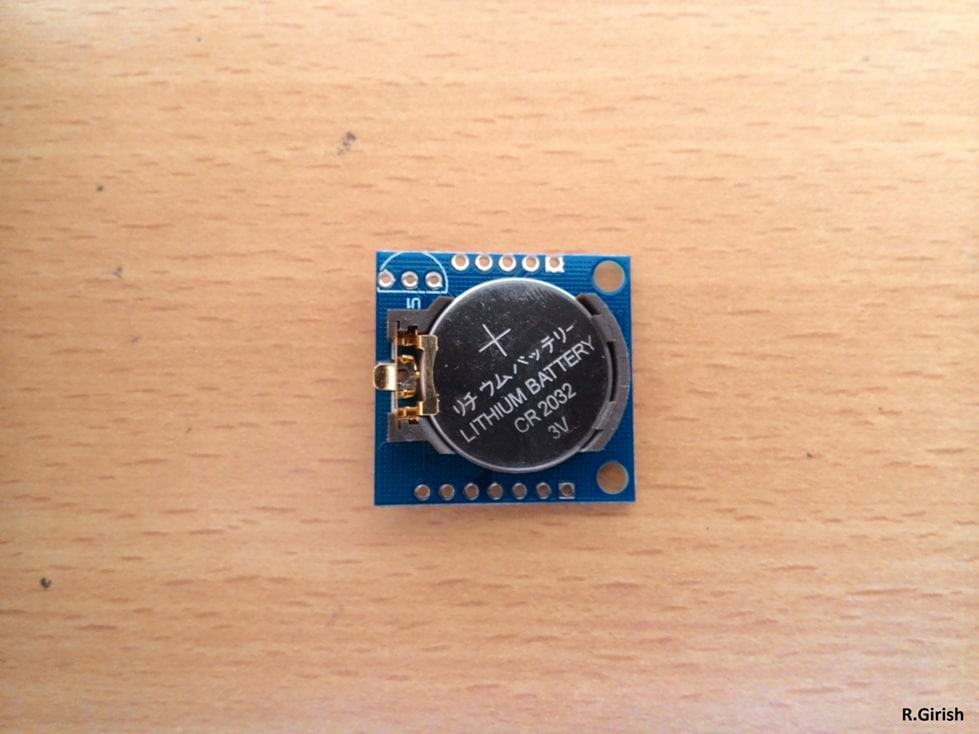
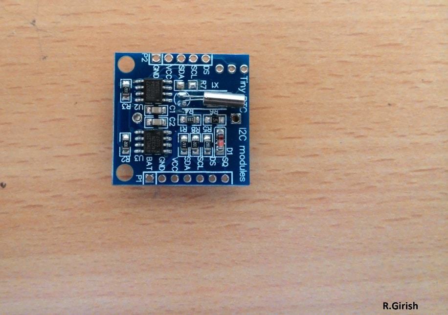
Most of the RTC modules come with battery (CR2032) at the time of purchase. There are different of size and models, the above illustrated may not be the same for you. But make sure the model number is DS1307. The code written in this post is only compatible with DS1307.
Now you know something about RTCs. Now let’s move on to the digital clock design. Before proceeding with this project you need to download the library from the following links and install on your IDE:
• DS1307RTC.h
Link: github.com/PaulStoffregen/DS1307RTC
• TimeLib.h
Link: github.com/PaulStoffregen/Time
Other two libraries would have been preinstalled on Arduino IDE, if you are on latest version.
• LiquidCrystal.h
• Wire.h
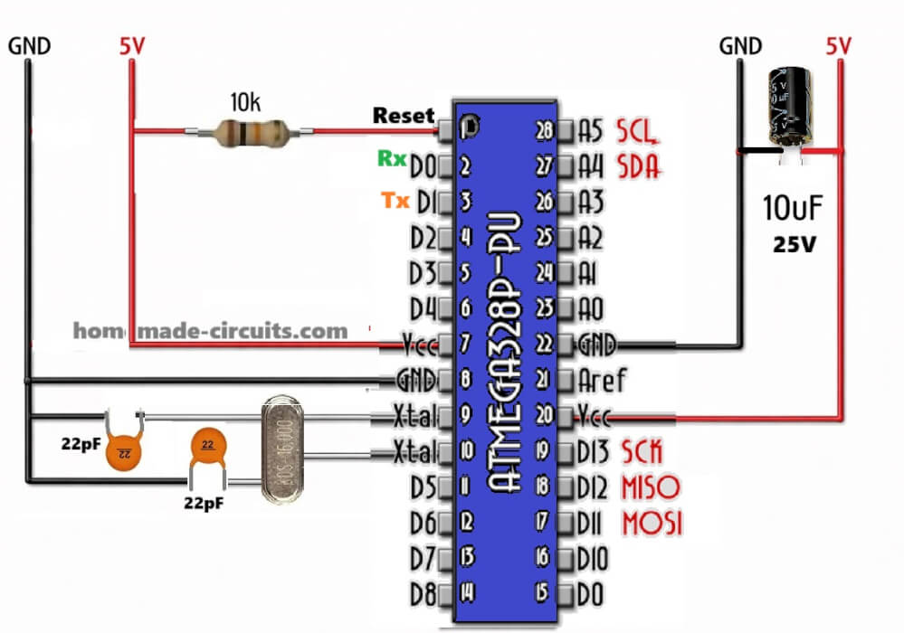
The Circuit:
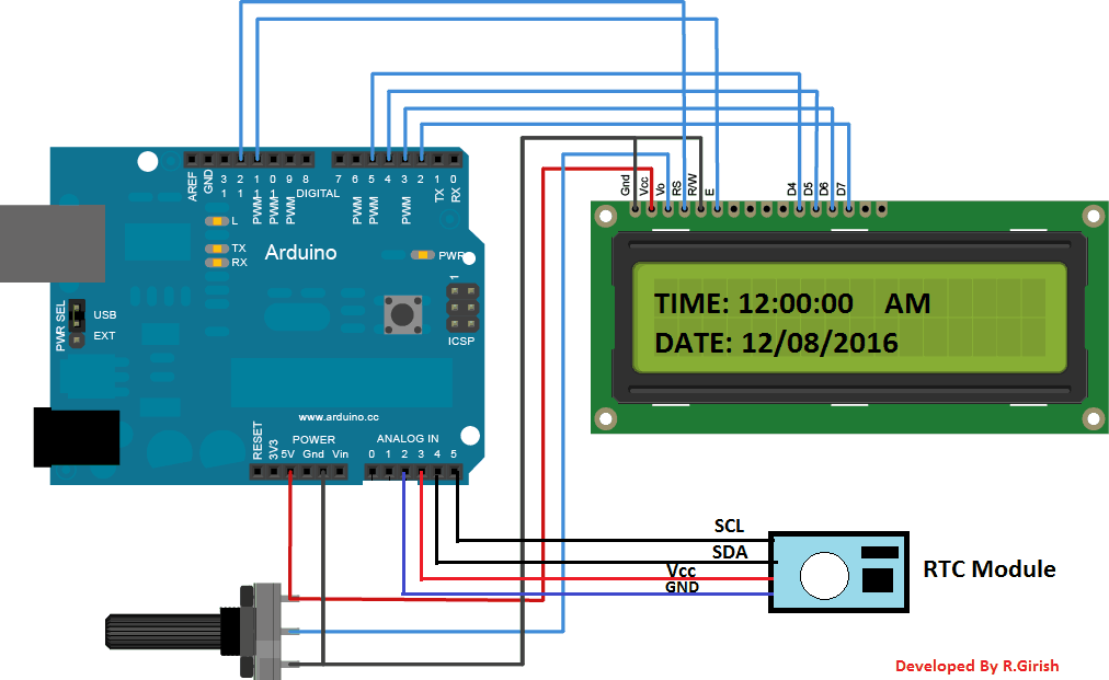
The circuit connection between arduino and LCD display is standard, which we can find similar connection on other LCD based projects. The only additional component is the RTC.
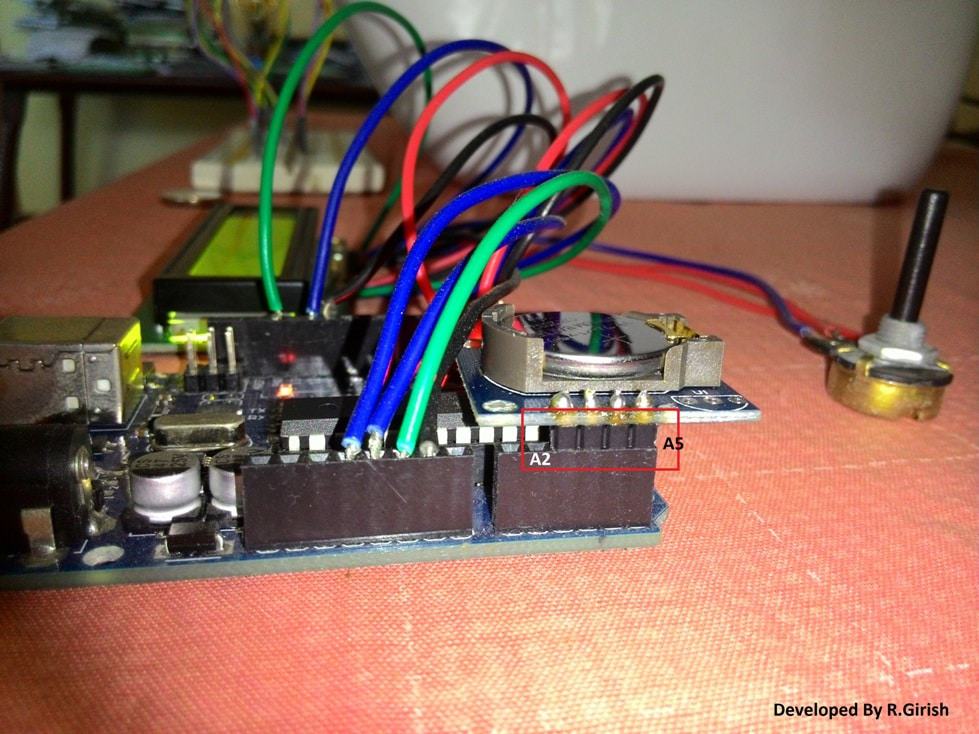
To reduce wire congestion during prototype, the RTC can be inserted to the analogue pins directly of the arduino. Solder the SCl, SDA, Vcc, and GND with male header pins and insert it A2 to A5 pins as shown in the prototype.
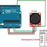
Author’s prototype:
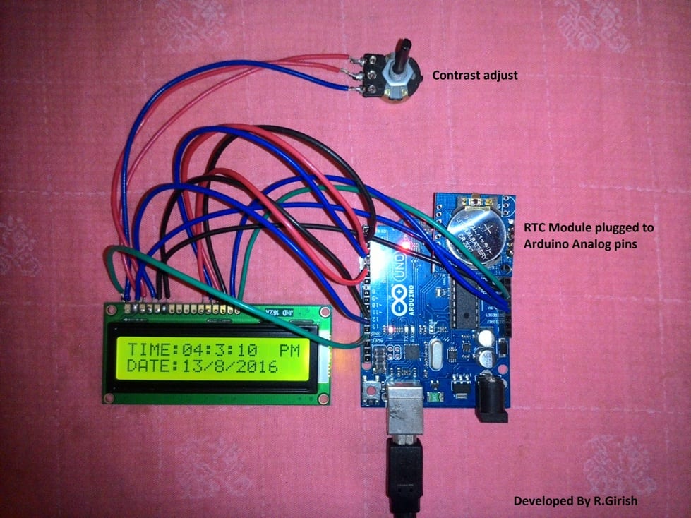
How to properly insert RTC on Arduino:
If your RTC has different pin locations and could not replicate as illustrated above, you can always use wires for connection. Now your hardware setup is complete, let’s move to the software part of the project.
How to set time:
Once the RTC module is programmed, it maintains the time even it is removed from the arduino. The battery should last at least a couple of years.
There is no button to adjust the time; the following program will set the time in RTC. The time automatically synchronized with time of your computer, while compiling the code, so make sure your computer is set to correct time, before uploading the programs.
Upload this “SetTime” code to set the time with RTC plugged in:
#include <Wire.h>

#include <TimeLib.h>

#include <DS1307RTC.h>

int P=A3; //Assign power pins for RTC

int N=A2;

const char *monthName[12] = {

"Jan", "Feb", "Mar", "Apr", "May", "Jun",

"Jul", "Aug", "Sep", "Oct", "Nov", "Dec"

};

tmElements_t tm;

void setup() {

pinMode(P,OUTPUT);

pinMode(N,OUTPUT);

digitalWrite(P,HIGH);

digitalWrite(N,LOW);

bool parse=false;

bool config=false;

// get the date and time the compiler was run

if (getDate(__DATE__) && getTime(__TIME__)) {

parse = true;

// and configure the RTC with this info

if (RTC.write(tm)) {

config = true;

}

}

Serial.begin(9600);

while (!Serial) ; // wait for Arduino Serial Monitor

delay(200);

if (parse && config) {

Serial.print("DS1307 configured Time=");

Serial.print(__TIME__);

Serial.print(", Date=");

Serial.println(__DATE__);

} else if (parse) {

Serial.println("DS1307 Communication Error :-{");

Serial.println("Please check your circuitry");

} else {

Serial.print("Could not parse info from the compiler, Time=\"");

Serial.print(__TIME__);

Serial.print("\", Date=\"");

Serial.print(__DATE__);

Serial.println("\"");

}

}

void loop() {

}

bool getTime(const char *str)

{

int Hour, Min, Sec;

if (sscanf(str, "%d:%d:%d", &Hour, &Min, &Sec) != 3) return false;

tm.Hour = Hour;

tm.Minute = Min;

tm.Second = Sec;

return true;

}

bool getDate(const char *str)

{

char Month[12];

int Day, Year;

uint8_t monthIndex;

if (sscanf(str, "%s %d %d", Month, &Day, &Year) != 3) return false;

for (monthIndex = 0; monthIndex < 12; monthIndex++) {

if (strcmp(Month, monthName[monthIndex]) == 0) break;

}

if (monthIndex >= 12) return false;

tm.Day = Day;

tm.Month = monthIndex + 1;

tm.Year = CalendarYrToTm(Year);

return true;

}
Once this code is uploaded, open the serial monitor and a success message should pop up saying the time has been set.
This signifies that your connection between the RTC and arduino is correct and time is set.
Now upload the following code for displaying the time in LCD.
//------------Program Developed by R.Girish-------//

#include <Wire.h>

#include <TimeLib.h>

#include <DS1307RTC.h>

#include <LiquidCrystal.h>

LiquidCrystal lcd(12, 11, 5, 4, 3, 2);

int P=A3;

int N=A2;

void setup() {

lcd.begin(16,2);

pinMode(P,OUTPUT);

pinMode(N,OUTPUT);

digitalWrite(P,HIGH);

digitalWrite(N,LOW);

}

void loop() {

tmElements_t tm;

lcd.clear();

if (RTC.read(tm))

{

if(tm.Hour>=12)

{

lcd.setCursor(14,0);

lcd.print("PM");

}

if(tm.Hour<12)

{

lcd.setCursor(14,0);

lcd.print("AM");

}

lcd.setCursor(0,0);

lcd.print("TIME:");

if(tm.Hour>12) //24Hrs to 12 Hrs conversion//

{

if(tm.Hour==13) lcd.print("01");

if(tm.Hour==14) lcd.print("02");

if(tm.Hour==15) lcd.print("03");

if(tm.Hour==16) lcd.print("04");

if(tm.Hour==17) lcd.print("05");

if(tm.Hour==18) lcd.print("06");

if(tm.Hour==19) lcd.print("07");

if(tm.Hour==20) lcd.print("08");

if(tm.Hour==21) lcd.print("09");

if(tm.Hour==22) lcd.print("10");

if(tm.Hour==23) lcd.print("11");

}

else

{

lcd.print(tm.Hour);

}

lcd.print(":");

lcd.print(tm.Minute);

lcd.print(":");

lcd.print(tm.Second);

lcd.setCursor(0,1);

lcd.print("DATE:");

lcd.print(tm.Day);

lcd.print("/");

lcd.print(tm.Month);

lcd.print("/");

lcd.print(tmYearToCalendar(tm.Year));

} else {

if (RTC.chipPresent()) {

lcd.setCursor(0,0);

lcd.print("RTC stopped!!!");

lcd.setCursor(0,1);

lcd.print("Run SetTime code");

} else {

lcd.clear();

lcd.setCursor(0,0);

lcd.print("Read error!");

lcd.setCursor(0,1);

lcd.print("Check circuitry!");

}

delay(500);

}

delay(500);

}


//------------Program Developed by R.Girish-------//
Once this is done you should see the time and date is displayed on LCD and running.
Note: The “SetTime” code is modified from example code of DS1307RTC to optimize wire connections for RTC module, uploading original code won’t set time.
Digital Alarm Clock Using Arduino
In this above I have explained how to build the basic Arduino clock using RTC module, in the following secion we investigate how this can be upgraded into a digital alarm clock circuit using Arduino.
There are some people who need no alarm clock, they wake up naturally and there are some people who wake up after alarm clock rings few times and there are some people who press snooze button a bunch of times and go for their college / work late with some excuses.
The proposed fun little alarm clock project may confront the problem with laziness during morning wake. Most alarm clocks have a snooze button and pre-determined cut-off time for alarm if user didn’t respond.
We designed this alarm clock without a lazy button (snooze button) and the alarm won’t turn off until the user push a button.
This clock can show time in 12 hour format and date in DD/MM/YYYY format.
The time and date will be showcased on 16 x 2 LCD display. An RTC or real time clock time module will take care of tracking the time and can retain correct time even after a long power cut.
There are 5 buttons provided who’s function will be explained shortly. The brain of the project Arduino can any model of your choice, we would recommend Arduino pro mini or Arduino nano because of its compact size.
Now let’s dive into schematics.
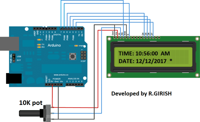
The above is the schematic is for Arduino to display connection, adjust the display contrast by rotating the 10K potentiometer.
The below is the rest of the circuit:
The circuit can be powered 9V 500mA wall adapter.
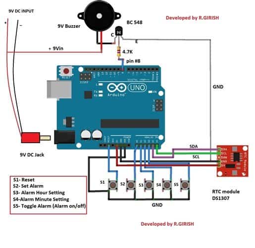
Functions of 5 buttons:
S1 - This is used for stop the alarm (it is also reset button).
S2 - Is used for setting alarm. By long pressing S2 you will get to alarm setting menu.
S3 - It is used to increment hours.
S4 – it is used to increment minutes.
S5 – Is used for toggling the alarm status. If “*” exists on LCD display on right side bottom corner the alarm is ON, if the “*” does not exists the alarm stats is OFF.
More detail on how to set alarm is explained at bottom of the article.
Download the library files below:
Link1: github.com/PaulStoffregen/DS1307RTC
Link2: github.com/PaulStoffregen/Time
Now, we have to set time to RTC module, the time will be synchronized from you PC to RTC module.
Upload the below code to set time and open Serial monitor:
//------------------------------------------------//
#include <Wire.h>
#include <TimeLib.h>
#include <DS1307RTC.h>
const char *monthName[12] = {
"Jan", "Feb", "Mar", "Apr", "May", "Jun",
"Jul", "Aug", "Sep", "Oct", "Nov", "Dec"
};
tmElements_t tm;
void setup() {
bool parse=false;
bool config=false;
// get the date and time the compiler was run
if (getDate(__DATE__) && getTime(__TIME__)) {
parse = true;
// and configure the RTC with this info
if (RTC.write(tm)) {
config = true;
}
}
Serial.begin(9600);
while (!Serial) ; // wait for Arduino Serial Monitor
delay(200);
if (parse && config) {
Serial.print("DS1307 configured Time=");
Serial.print(__TIME__);
Serial.print(", Date=");
Serial.println(__DATE__);
} else if (parse) {
Serial.println("DS1307 Communication Error :-{");
Serial.println("Please check your circuitry");
} else {
Serial.print("Could not parse info from the compiler, Time=\"");
Serial.print(__TIME__);
Serial.print("\", Date=\"");
Serial.print(__DATE__);
Serial.println("\"");
}
}
void loop() {
}
bool getTime(const char *str)
{
int Hour, Min, Sec;
if (sscanf(str, "%d:%d:%d", &Hour, &Min, &Sec) != 3) return false;
tm.Hour = Hour;
tm.Minute = Min;
tm.Second = Sec;
return true;
}
bool getDate(const char *str)
{
char Month[12];
int Day, Year;
uint8_t monthIndex;
if (sscanf(str, "%s %d %d", Month, &Day, &Year) != 3) return false;
for (monthIndex = 0; monthIndex < 12; monthIndex++) {
if (strcmp(Month, monthName[monthIndex]) == 0) break;
}
if (monthIndex >= 12) return false;
tm.Day = Day;
tm.Month = monthIndex + 1;
tm.Year = CalendarYrToTm(Year);
return true;
}
//----------------------------------------//
Now you have successfully set time to RTC
Next, you need to upload the following main code:
//------------Program Developed by R.Girish-------//
#include <LiquidCrystal.h>
#include <DS1307RTC.h>
#include <TimeLib.h>
#include <Wire.h>
#include <EEPROM.h>
const int rs = 7;
const int en = 6;
const int d4 = 5;
const int d5 = 4;
const int d6 = 3;
const int d7 = 2;
const int buzzer = 8;
boolean alarm = false;
boolean outloop = true;
const int setAlarm = A0;
const int Hrs = A1;
const int Min = A2;
const int ok = A3;
const int HrsADD = 0;
const int MinADD = 1;
const int ALsave = 2;
int HrsVal = 0;
int MinVal = 0;
int H = 0;
int M = 0;
int S = 0;
int i = 0;
int j = 0;
int k = 0;
LiquidCrystal lcd(rs, en, d4, d5, d6, d7);
void setup()
{
Serial.begin(9600);
lcd.begin(16, 2);
pinMode(buzzer, OUTPUT);
pinMode(setAlarm, INPUT);
pinMode(Hrs, INPUT);
pinMode(Min, INPUT);
pinMode(ok, INPUT);
digitalWrite(setAlarm, HIGH);
digitalWrite(Hrs, HIGH);
digitalWrite(Min, HIGH);
digitalWrite(ok, HIGH);
}
void loop()
{
tmElements_t tm;
lcd.clear();
if (EEPROM.read(ALsave) == false)
{
lcd.setCursor(15, 1);
lcd.print("");
}
if (EEPROM.read(ALsave) == true)
{
lcd.setCursor(15, 1);
lcd.print(F("*"));
}
if (RTC.read(tm))
{
if (tm.Hour >= 12)
{
lcd.setCursor(14, 0);
lcd.print("PM");
}
if (tm.Hour < 12)
{
lcd.setCursor(14, 0);
lcd.print("AM");
}
lcd.setCursor(0, 0);
lcd.print("TIME:");
H = tm.Hour;
if (tm.Hour > 12)
{
if (tm.Hour == 13)
{
lcd.print("01");
}
if (tm.Hour == 14)
{
lcd.print("02");
}
if (tm.Hour == 15)
{
lcd.print("03");
}
if (tm.Hour == 16)
{
lcd.print("04");
}
if (tm.Hour == 17)
{
lcd.print("05");
}
if (tm.Hour == 18)
{
lcd.print("06");
}
if (tm.Hour == 19)
{
lcd.print("07");
}
if (tm.Hour == 20)
{
lcd.print("08");
}
if (tm.Hour == 21)
{
lcd.print("09");
}
if (tm.Hour == 22)
{
lcd.print("10");
}
if (tm.Hour == 23)
{
lcd.print("11");
}
}
else
{
lcd.print(tm.Hour);
}
M = tm.Minute;
S = tm.Second;
lcd.print(":");
lcd.print(tm.Minute);
lcd.print(":");
lcd.print(tm.Second);
lcd.setCursor(0, 1);
lcd.print("DATE:");
lcd.print(tm.Day);
lcd.print("/");
lcd.print(tm.Month);
lcd.print("/");
lcd.print(tmYearToCalendar(tm.Year));
} else {
if (RTC.chipPresent())
{
lcd.setCursor(0, 0);
lcd.print("RTC stopped!!!");
lcd.setCursor(0, 1);
lcd.print("Run SetTime code");
} else {
lcd.clear();
lcd.setCursor(0, 0);
lcd.print("Read error!");
lcd.setCursor(0, 1);
lcd.print("Check circuitry!");
}
}
if (digitalRead(setAlarm) == LOW)
{
setALARM();
}
if (H == EEPROM.read(HrsADD) && M == EEPROM.read(MinADD) && S == 0)
{
if (EEPROM.read(ALsave) == true)
{
sound();
}
}
if (digitalRead(ok) == LOW)
{
if (EEPROM.read(ALsave) == true)
{
EEPROM.write(ALsave, 0);
alarm = false;
delay(1000);
return;
}
if (EEPROM.read(ALsave) == false)
{
EEPROM.write(ALsave, 1);
alarm = true;
delay(1000);
return;
}
}
delay(1000);
}
void setALARM()
{
HrsVal = EEPROM.read(HrsADD);
MinVal = EEPROM.read(MinADD);
lcd.clear();
lcd.setCursor(0, 0);
lcd.print(F(">>>>SET ALARM<<<"));
lcd.setCursor(0, 1);
lcd.print(F("Hrs:"));
lcd.print(EEPROM.read(HrsADD));
lcd.print(F(" Min:"));
lcd.print(EEPROM.read(MinADD));
delay(600);
while (outloop)
{
if (HrsVal > 23)
{
HrsVal = 0;
lcd.clear();
lcd.setCursor(0, 0);
lcd.print(F(">>>>SET ALARM<<<"));
lcd.setCursor(0, 1);
lcd.print(F("Hrs:"));
lcd.print(HrsVal);
lcd.print(F(" Min:"));
lcd.print(MinVal);
}
if (MinVal > 59)
{
MinVal = 0;
lcd.clear();
lcd.setCursor(0, 0);
lcd.print(F(">>>>SET ALARM<<<"));
lcd.setCursor(0, 1);
lcd.print(F("Hrs:"));
lcd.print(HrsVal);
lcd.print(F(" Min:"));
lcd.print(MinVal);
}
if (digitalRead(Hrs) == LOW)
{
HrsVal = HrsVal + 1;
lcd.clear();
lcd.setCursor(0, 0);
lcd.print(F(">>>>SET ALARM<<<"));
lcd.setCursor(0, 1);
lcd.print(F("Hrs:"));
lcd.print(HrsVal);
lcd.print(F(" Min:"));
lcd.print(MinVal);
delay(250);
}
if (digitalRead(Min) == LOW)
{
MinVal = MinVal + 1;
lcd.clear();
lcd.setCursor(0, 0);
lcd.print(F(">>>>SET ALARM<<<"));
lcd.setCursor(0, 1);
lcd.print(F("Hrs:"));
lcd.print(HrsVal);
lcd.print(F(" Min:"));
lcd.print(MinVal);
delay(250);
}
if (digitalRead(setAlarm) == LOW)
{
EEPROM.write(HrsADD, HrsVal);
EEPROM.write(MinADD, MinVal);
lcd.clear();
lcd.setCursor(0, 0);
lcd.print(F("Alarm is Set for"));
lcd.setCursor(0, 1);
lcd.print(EEPROM.read(HrsADD));
lcd.print(F(":"));
lcd.print(EEPROM.read(MinADD));
lcd.print(F(" Hrs"));
delay(1000);
outloop = false;
}
}
outloop = true;
}
void sound()
{
lcd.clear();
lcd.setCursor(0, 0);
lcd.print("Wakey Wakey !!!");
lcd.setCursor(0, 1);
lcd.print("Its Time now.....");
for (j = 0; j < 10; j++)
{
for (i = 0; i < 2 ; i++)
{
digitalWrite(buzzer, HIGH);
delay(150);
digitalWrite(buzzer, LOW);
delay(150);
}
delay(400);
}
for (k = 0; k < 10; k++)
{
for (i = 0; i < 4 ; i++)
{
digitalWrite(buzzer, HIGH);
delay(150);
digitalWrite(buzzer, LOW);
delay(150);
}
delay(250);
}
while (true)
{
digitalWrite(buzzer, HIGH);
delay(150);
digitalWrite(buzzer, LOW);
delay(150);
}
}
//------------Program Developed by R.Girish-------//
After uploading the above code you must see correct time and date running on the display.
Now let’s see how to set alarm:
• Long press S2 until you can see Alarm menu.
• Press S3 and S4 to adjust hours and minutes respectively.
• After the desired time set, press S2 once again. It will say “The alarm is set for xx:xx hours”.
• If the alarm is ON you can see “*” symbol on the display, if the alarm is OFF there will be no “*” symbol.
• You can turn on / off the alarm by pressing S5 for half a second. Don’t long press until “*” vanishes (it comes back again), just press half a second long to toggle alarm status.
IMPORTANT NOTE:
The most common mistake while setting an alarm on any clock is unintentional toggling AM / PM, which results in not ringing of alarm at our desire time.
To counter this issue the proposed alarm clock setting is designed on 24 hour clock format.
The time displayed on the LCD will be 12 hour with AM / PM format but, when you set an alarm with this project you have to set in 24 hour format from 0 to 23 hours.
For example: if you want to set alarm at 9:00 PM you have to set 21 hours and 0 minutes. For, 5 AM: 5 hours and 0 minutes and so on.
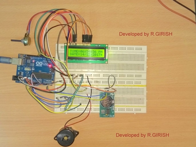
Author’s prototype:
Do you like this project? Have any question regarding this project, feel free to express in the comment, you may receive a quick reply.
Video Clip:


Comments
Hello sir
Can we set time & date externally by tactile switch with RTC & mcu ?
Nitesh, yes you can use tactile switches as shown in the last image…
Dear
With RTC DS1307 & mcu is it possible to show DATE in 00 00 0000 format & time in 00 00 00 format .Total 8 seg for date display & 6 seg for time display.
is it possible to set time & date with MCU ? . i want to need externally Tactile switch for set date & time .if possible show me schematics with any mcu or Arduino.
Nitesh, I think yes it is possible, but since I am not an Arduino expert so giving further details can be difficult for me in this regards.
Thanks