In this article I have explained how to make a simple 2-step Arduino programmable timer circuit, which can be used to switch an electrical load ON/OFF with independently adjustable ON and OFF timings.
For example if you want a light to remain ON for 24 hours and OFF for 2 hours, you can simply do this through a quick modification in the program code. In the same way you can customize the output timings to any other desired set of time intervals by changing the code appropriately.
You just have to compile and upload the following code to your Arduino board and start the timer function as per your specific application needs.
Program Code
void setup(){
pinMode(13, OUTPUT);
}
void loop(){

digitalWrite(13, HIGH);
delay(86400000);
digitalWrite(13, LOW);
delay(3600000);
}
In the above example code the lines delay(86400000); and delay(3600000); determine the output ON and OFF delay time intervals respectively, in milliseconds. Here, the figure 86400000 milliseconds corresponds to 24 hours, while 3600000 exhibits 1 hour delay.
You can customize these two values as per your personal preference to get the required output delays.
Once setup and powered, the Arduino will continue switching between the two step ON/OFF timing sequence. as long as power remains applied to the system.
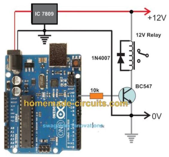
Circuit Diagram
The complete circuit diagram along with the Arduino connections can be witnessed in the following diagram:
Advanced Programmable Timer Version
Here is the most advanced version of the above programmable timer code using non-blocking millis() technique so Arduino remains fully responsive and can do other tasks while managing the timer.
Full Code
const int outputPin = 13;

unsigned long onTime = 86400000;   // ON time in milliseconds (24 hours)
unsigned long offTime = 3600000;   // OFF time in milliseconds (1 hour)

unsigned long previousMillis = 0;
bool outputState = false;

void setup() {
  pinMode(outputPin, OUTPUT);
  Serial.begin(9600);
}

void loop() {
  unsigned long currentMillis = millis();

  if (outputState == false) {
    // Currently OFF, check if it's time to turn ON
    if (currentMillis - previousMillis >= offTime) {
      outputState = true;
      digitalWrite(outputPin, HIGH);
      previousMillis = currentMillis;
      Serial.println("Output turned ON");
    }
  }
  else {
    // Currently ON, check if it's time to turn OFF
    if (currentMillis - previousMillis >= onTime) {
      outputState = false;
      digitalWrite(outputPin, LOW);
      previousMillis = currentMillis;
      Serial.println("Output turned OFF");
    }
  }

  // You can do other tasks here without being blocked by delay()
}
Full Explanation
Now, let us understand the above most advanced programmable timer using Arduino that works without blocking the processor so that we can do other things while timer is running.
This is very useful because using delay() makes Arduino freeze and do nothing else.
First, we define some variables like this:
outputpin = 13 this is the pin number where we will connect the load or led or anything we want to control
ontime = 86400000 this is on duration in milliseconds 24 hours
offtime = 3600000 this is off duration in milliseconds 1 hour
previousmillis = 0 this will remember last time when we switched state
outputstate = false initially we start with output off
in setup() function, we do this:
We set pin 13 as output by calling pinmode(outputpin, output)
We start serial communication by serial.
begin(9600) so that we can see debug messages on serial monitor
Now in loop(), we read current time from arduino with currentmillis = millis().
Then, we do check like this:
When output is off outputstate == false
We check that if currentmillis - previousmillis >= offtime, then off time has passed, then we turn on output by digitalwrite(outputpin, high)
We set outputstate = true and previousmillis = currentmillis
Also, we print "output turned on" to serial monitor
When output is on outputstate == true, we check that if currentmillis - previousmillis >= ontime then on time has passed, then we turn off output by digitalwrite(outputpin, low).
We set outputstate = false and previousmillis = currentmillis.
Also, we print "output turned off" to serial monitor
Now we can do other tasks without Arduino being stuck or frozen
This method is much better than using delay() because delay() just stops everything and Arduino cannot do anything else while waiting.
But with millis() method, arduino stays alive and responsive.
So now we can read sensors, send serial data, or communicate with other devices without any problem.
You can change ontime or offtime value at the top
For example:
ontime = 60000 on for 1 minute
offtime = 300000 off for 5 minutes
You just change the number and it works that is all.
If you want us to make this timer adjustable in run-time by serial monitor or save settings in eeprom then we can do that too.
Then you will not need to change code again and again.
This is now the most advanced super flexible non-blocking timer you can ever make on Arduino.
It works reliably and stays ready for more functions in parallel.
Arduino One-Shot Timer Circuit
If you don't want the timer to loop through the two step timer, instead want the timer to be a one-shot type, which will switch OFF permanently after the set delay, you can apply the following code:
Full Code:
int led = 13

unsigned long delay_time = 10000  // 10 seconds
unsigned long delay_start = 0  // the time the delay started
bool delay_running = false  // true if still waiting for delay to finish

void setup()
{
  pinmode(led, output)  // we initialize the digital pin as output
  digitalwrite(led, high)  // now we turn led on

  delay_start = millis()  // we record current time as start of delay
  delay_running = true  // we mark that delay is running
}

void loop()
{
  unsigned long current_millis = millis()  // we read current time every loop

  if delay_running == true and (current_millis - delay_start) >= delay_time
  {
    delay_running = false  // now delay finished, this is single shot, so only happens once
    digitalwrite(led, low)  // we turn led off
  }

  // now, we can do other tasks here without being blocked by delay
}
Explanation
Now let us explain this improved code for the one-shot timer step by step.
First we declare variables.
led = 13 This is the pin where the LED is connected on the Arduino board.
delay_time = 10000 This is how long we want to keep the LED on in milliseconds; that is 10 seconds.
delay_start = 0 This will store the time when the delay starts.
delay_running = false This tells us if the delay is running or finished.
In the setup() function, we do this.
We set pin 13 as output by calling pinMode(led, output).
Then we turn the LED on by digitalWrite(led, high).
We record the current time by millis() into delay_start.
We set delay_running = true to mark that the delay is now running.
In the loop() function, we do this every time Arduino loops.
We read the current time from millis() into current_millis.
Then we check that if delay_running == true and (current_millis - delay_start) >= delay_time, then delay time has finished.
If that is true, then we set delay_running = false, meaning the delay finished. Then we turn the LED off by digitalWrite(led, low).
Now because we use millis() instead of delay(), Arduino never gets stuck or blocked.
So now we can add more code here to read sensors or send serial data or do other tasks while this timer is running in the background.
This method is way better than using simple delay(10000) because delay() would stop everything for 10 seconds.
But with this millis() method, Arduino keeps doing other things and remains fully responsive.
You can easily change the delay_time variable to any number you want.
for exampledelay_time = 5000 Now it will keep the LED on for 5 seconds.
delay_time = 30000; now it will keep the LED on for 30 seconds.
You just change the number and it works, that is all.
If you want us to make this timer adjustable by serial input or save the state in EEPROM so that it works even after power-off, we can do that too.
Then you will not need to change code manually every time. This is now an improved version of your programmable single-shot timer using millis(). It is reliable, non-blocking, and easy to customize.
If you want a discretely designed version of an identical programmable timer circuit, you can opt for this circuit
Parts Required for the Arduino Programmable Timer Circuit
- Arduino UNO Board = 1
- IC 7809 = 1
- BC547 = 1
- 1N4007 Diode = 1
- 10k 1/4 w resistor = 1
- Relay 12V/400 ohm/SPDT/5 amp = 1
- 12V AC to DC Adapter = 1
Using EEPROM to Handle Power Cut Problems
Full Code:
#include <EEPROM.h>   // Include EEPROM library for permanent storage

// -------------------- USER SETTINGS --------------------

const int outputPin = 13;   // LED connected to pin 13

// Set your ON and OFF time here (in milliseconds)
unsigned long onTime  = 240000;   // 4 minutes ON
unsigned long offTime = 60000;    // 1 minute OFF

// -------------------- GLOBAL VARIABLES --------------------

unsigned long previousMillis = 0;   // Stores last time reference
unsigned long remainingTime = 0;    // Stores how much time is left in current state

bool outputState = false;           // false = OFF, true = ON

// EEPROM memory locations
#define STATE_ADDR 0   // Address to store ON/OFF state
#define TIME_ADDR  10  // Address to store remaining time

// --------------------------------------------------------
// Function to save current state and remaining time
// into EEPROM so it survives power failure
// --------------------------------------------------------
void saveData()
{
  EEPROM.put(STATE_ADDR, outputState);     // Store ON/OFF state
  EEPROM.put(TIME_ADDR, remainingTime);    // Store remaining time
}

// --------------------------------------------------------
// Function to load saved state and time from EEPROM
// when Arduino restarts
// --------------------------------------------------------
void loadData()
{
  EEPROM.get(STATE_ADDR, outputState);     // Read saved ON/OFF state
  EEPROM.get(TIME_ADDR, remainingTime);    // Read saved remaining time

  // Safety check:
  // If stored value is garbage or too big,
  // reset remainingTime to zero
  if (remainingTime > onTime && remainingTime > offTime)
  {
    remainingTime = 0;
  }
}

// --------------------------------------------------------
void setup()
{
  pinMode(outputPin, OUTPUT);  // Set LED pin as output
  Serial.begin(9600);          // Start serial monitor

  loadData();  // Load previous saved data from EEPROM

  // If no valid data found, start fresh
  if (remainingTime == 0)
  {
    outputState = false;       // Start from OFF
    remainingTime = offTime;   // First cycle will be OFF duration
  }

  // Apply the stored state to the LED
  digitalWrite(outputPin, outputState ? HIGH : LOW);

  // Set current millis as starting reference
  previousMillis = millis();
}

// --------------------------------------------------------
void loop()
{
  unsigned long currentMillis = millis();  // Get current running time

  // Check if required time has passed
  if (currentMillis - previousMillis >= remainingTime)
  {
    // Toggle state (ON becomes OFF, OFF becomes ON)
    outputState = !outputState;

    // Apply new state to LED
    digitalWrite(outputPin, outputState ? HIGH : LOW);

    // Load next duration based on state
    if (outputState == true)
    {
      remainingTime = onTime;   // If turned ON → load ON time
    }
    else
    {
      remainingTime = offTime;  // If turned OFF → load OFF time
    }

    // Reset time reference
    previousMillis = currentMillis;

    // Save updated state and time to EEPROM
    saveData();

    // Debug message
    Serial.println(outputState ? "Output ON" : "Output OFF");
  }

  // No delay() used → non-blocking timer
}
We made this version because power cut could mess things up, so now this one handles that.
The Normal Timer Problem
Let us say LED ON for 4 minutes. At 2 minutes power goes OFF. Now when power comes back, then timer starts again from zero, like nothing happened, so that is wrong behavior. That is the usual issue we see in our homes.
What We Changed Here
We however, store two main things inside EEPROM, since EEPROM does not forget even if power goes away.
We store:
- Current state, ON or OFF.
- Remaining time, how much still left.
So now when power comes back, then Arduino reads EEPROM first, not restarting blindly. Therefore it continues from where it stopped.
EEPROM does not erase when power is removed, so that is the key point here.
Main Variables
We have:
- onTime = time LED stays ON.
- offTime = time LED stays OFF.
- remainingTime = how much time still pending.
- outputState = whether LED is ON or OFF.
- previousMillis = reference starting point.
When First Power ON happens
If EEPROM does not contain valid stored time, then it assumes fresh start. It starts from OFF state.
It sets remainingTime = offTime. So that becomes the starting cycle.
During Normal Operation
Loop keeps checking this condition: currentMillis - previousMillis >= remainingTime
If that becomes true, then state changes. If LED was ON then it goes OFF, if it was OFF then it goes ON.
Then next duration loads, onTime or offTime. Moreover it saves new state and new remainingTime into EEPROM again. So memory always stays updated before next cycle.
During Power Failure
Let us take example. ON time = 4 minutes. At 2 minutes power goes OFF.
Since EEPROM was already updated earlier, then it already has:
outputState = ON
remainingTime = balance ON time
So now when power returns, then Arduino reads that stored data first. LED turns ON immediately, because state says ON. It continues only the leftover time, not full 4 minutes again.
After that finishes, then normal cycle continues like usual.


Comments
Dear Sir;
I am in need of Arduino controlled reverse and forward relay controlled project details.
Following are the steps:-
1. After power ON, only after pushing ON push button (PB1), after 15 seconds, both relay1 (Motor1) and relay2 (Motor2) will start automatically simultaneously and stopped simultaneously, by pushing OFF push button (PB2) .
2. Relay3 (Motor3) will remain stopped, unless and until we press direction change push button (PB3).
3. When we will press PB3, relay2 stops and relay3 will ON after a timing gap of 15 seconds. Both relay2 and relay3 are interlocked. And stopped through PB2.
4. Along with PB3, there is also provision for a proximity switch (PB3 OR proximity switch) to change direction as per step number 3.
5. All three relay1, relay2 and relay3 will start with PB1 and stopped with PB2.
6. Relay1 is controlled with PB1 and PB2 only.
Thanks in advance for your kind guidance and support.
Sanjiv Mohbansi
sbmohbansi@gmail.com
Please Sir can you elaborate on how to load a bootloader to ATMEGA 328?
Thank you
Sorry Dan, I have no idea about it.
Thank you very much Sir for your quick responds. its exactly what I need.
You are welcome Dan!
wow Thanks a lot Swagatam the code (sketch) is working very well.
Glad it’s working Dan, hope you succeed with the project.