In this post I have explained how to make a simple IC 555 based alternate relay timer circuit for toggling a couple of loads alternately with a specified length of delay, as determined by the calculated values of the relevant components. The idea was requested by Mr. Sanjoy.
Circuit Objectives and Requirements
- I am a regular reader of your excellent posts. Here I would like to request a circuit design.
- I am trying to build a laboratory paper coating set up for which I am going to employ 2000 watts hair driers for drying of the coated paper.
- The problem is that those driers can't be run continuously.
- Therefore I decided to use two driers alternately for three minutes each. But alternate switching of these driers manually always is tiresome.
- So I request a circuit which will be able to switch on and switch off the the driers alternately and automatically for a preset period of time and continue doing this until switched off.
The Design
Referring to the below shown alternate switching relay circuit, or we can also call it an alternate switching flasher circuit, the idea may be understood with the help of the attached explanation.
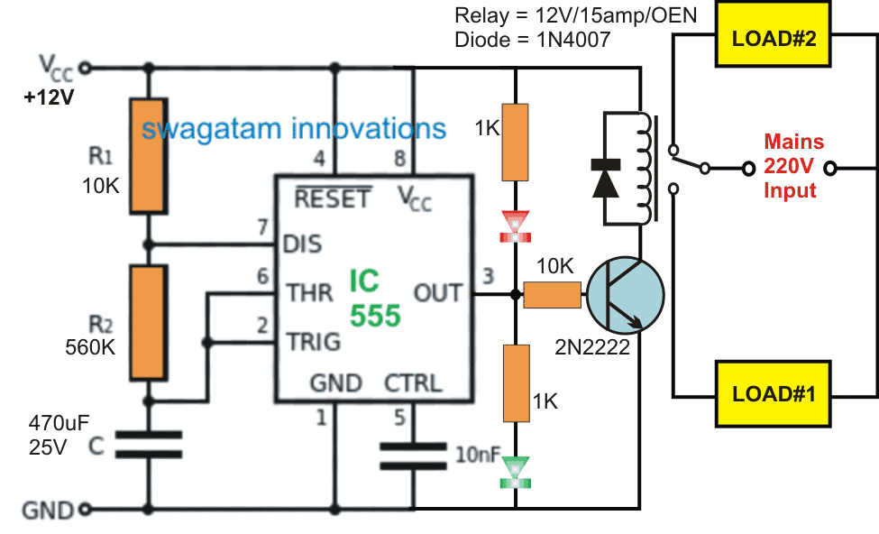
The circuit is built around a standard IC 555 astable configuration, which basically produces an alternating high and low or an alternating 12V and zero volt at its pin#3 when switched ON.
This alternately switching output accompanies certain delay between its ON/OFF switching as determined by the component values of R1, R2, and C.
In the proposed design the values of these timing components are suitably calculated to produce an approximately 50% duty cycle, and having a delay length of around 180 seconds or 3 minutes.
With the shown arrangement, only the value of the 470uF capacitor needs to be altered for achieving other preferred time delays across the output pin#3.
The pin#3 can be seen connected with a transistor relay driver stage which responds to the high/low pulses from the pinout and accordingly switches the relay contacts across the N/C and N/O contacts.
Since the two loads are connected across these two contacts of the relay, these are also alternately switched from ON to OFF and vice versa with a delay of 3 minutes between each switching.
The two LEDs connected across the supply pins and the pin#3 of the IC helps to indicate which load may be in the switched ON or OFF position at a given instant.
The above explained alternate switching relay timer circuit can be also implemented for other identical applications and the ON/OFF periods can be independently adjusted for achieving different ON/OFF sequences, by suitably altering the R1/R2 timing components of the astable.
Calculations for R1, R2, and C1 in the 555 Timer Astable Circuit:
Let's say you want the both the loads to switch ON and OFF alternately with a time difference of exactly 50 minutes, then you can calculate it as given below:
The goal is to design the circuit to operate at a 50% duty cycle with an ON time of 50 minutes and an OFF time of 50 minutes.
Formulas:
Frequency (f):
f = 1 / T
Period (T):
T = (R1 + 2R2) × C1 × 1.44
Duty Cycle (D):
D = (R1 + R2) / (R1 + 2R2) × 100%
Data in Hand:
ON Time (T_ON) = 50 minutes = 50 × 60 = 3000 seconds
OFF Time (T_OFF) = 50 minutes = 50 × 60 = 3000 seconds
Total Period (T) = T_ON + T_OFF = 6000 seconds
Duty Cycle (D) = 50%
Step-by-Step Calculations:
Step 1: Calculate Frequency:
f = 1 / T = 1 / 6000 = 0.0001667 Hz
Step 2: Select C1:
You will choose a practical value for C1. For long timing a high capacitance is suitable.
Assume:
C1 = 100 µF = 0.0001 F
Step 3: Calculate R1 + 2R2:
Rearranging the formula:
R1 + 2R2 = T / (1.44 × C1)
Substituting the values:
R1 + 2R2 = 6000 / (1.44 × 0.0001)
R1 + 2R2 = 6000 / 0.000144
R1 + 2R2 = 41,666,667 Ω ≈ 41.67 MΩ
Step 4: Split R1 and R2 for 50% Duty Cycle:
For D = 50%, R1 = R2.
R1 + 2R2 = 41.67 MΩ
R1 + 2R1 = 41.67 MΩ
3R1 = 41.67 MΩ
R1 = 41.67 / 3 ≈ 13.89 MΩ
R2 = R1 = 13.89 MΩ
Verification of ON and OFF Times:
ON Time (T_ON):
T_ON = 0.693 × (R1 + R2) × C1
T_ON = 0.693 × (13.89 + 13.89) × 0.0001
T_ON = 0.693 × 27.78 × 0.0001
T_ON = 0.001923 seconds ≈ 3000 seconds (Correct)
OFF Time (T_OFF):
T_OFF = 0.693 × R2 × C1
T_OFF = 0.693 × 13.89 × 0.0001
T_OFF = 0.000962 seconds ≈ 3000 seconds (Correct)
Final Component Values:
R1 = 13.89 MΩ
R2 = 13.89 MΩ
C1 = 100 µF
This configuration will give you an IC 555 astable circuit with a 50% duty cycle and an ON time of 50 minutes and an OFF time of 50 minutes for a total period of 100 minutes.


Comments
hi swagatam I need a circuit that operate timer on interval of 45 mins on/off switch, pls kindly help.
Hi Adewale, you can try the following circuit
https://www.homemade-circuits.com/how-to-make-simple-versatile-timer/
remove the feedback link, and set the pot to get 45 minute time intervals.
pin#3 can be configured with a relay driver stage
I need a circuit that will time the duration of an induction heater. The heater run time can be from 1 to 30 seconds, depending upon part size and configuration, at which time it turns off, shutting off the power relay to the heater. It would then trip a second relay with operates a solenoid to remove the part from the heater and reset everything to the initial state. A push button would initiate the heating/part ejection cycle.
what will be the operating voltage rating for the solenoid?
which software is good for sumulation???