In this post I have explained a simple homemade electric cloth dryer circuit using iron heater coil assembly which can be used for drying clothes at home during rainy season or overcast conditions. The idea was requested by Mr. Nelson.
Circuit Objectives and Requirements
- I have read through some of the topics explained at your website and highly impressed with your in depth knowledge in this area and your willingness to share it with the world.
- I feel you are the exact person to approach for advice/help as I have been having an idea to develop something that can dry cloths during rainy season.
- It is an equipment which will have heating coils similar to a room heater and dry cloths by blowing hot air (Electrically powered).
- Kindly advice how to get a drawing created as I would like make a prototype and study the market to see if I can start selling it.
The Design
A cloth dryer using home electricity can be costly as it would consume a heck lot of electricity and reflect the same in our utility bills.
Therefore the main issue that needs to be observed is the efficiency level of the system through which the most economical output may be achieved.
Using a fan blower and heater coil for drying clothes could make the design highly inefficient since applying breeze would tend to force the heater coil to cool causing higher amount of electricity consumption, therefore this idea could result in an inefficient and a costlier design.
The idea should be to heat the clothes by keeping them at a very close proximity with the heating coil and making sure that the clothes do not directly come in contact with the clothes, an example set up may be seen below:
Circuit Diagram
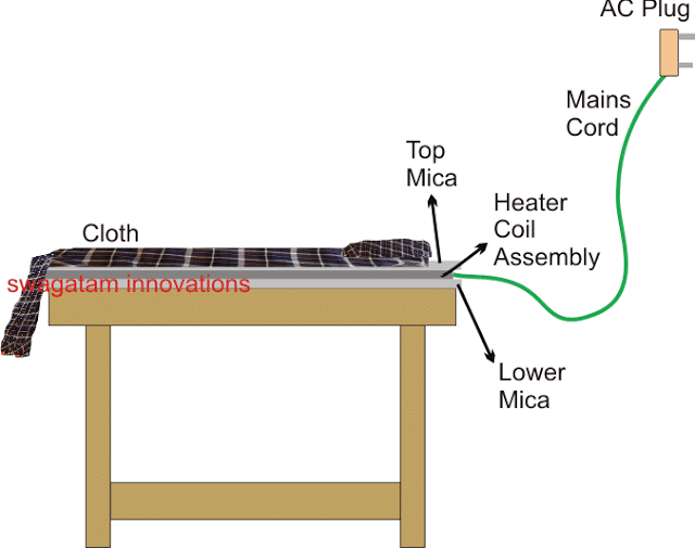
Here we see a flat platform which has series of heating coil spread across the whole area of the table.
Instead of hanging the clothes, these are spread flat over this table or platform for initiating the drying process.
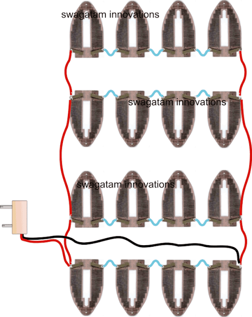
For the heating coils, we simply use 4 nos of iron coils in series each rated at 1000 watts, and we further add 4 such series assemblies in parallel to make an overall 1000 watt rated series/ parallel heater coil configuration, as shown below:
Wiring the Heater Coils
For making a homemade cloth dryer circuit, we can install the above shown heater coil assembly over a wooden table having a mica sheet covered on its surface. The Mica sheet should be thick enough and cover the entire area of the coil assembly so that the coils remain perfectly isolated from the wooden table.
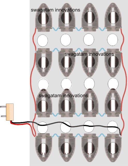
On top of this coil we place another similar mica sheet. But here we make sure that the sheet is punched with holes so that heat is able to dissipate from these holes and enforce the drying process for the clothes which are supposed to be laid down on top of this mica sheet.
Preferably these holes must be smaller in diameter but larger in quantity to ensure proper isolation of the cloth from the heater coil yet maximum exposure to the emanating heat from the coil assembly.
The arrangement may be examined with the following figure:
Using Mica for Insulation and Heat
Using a Blower Fan for Drying Clothes
If you find the above idea inappropriate, and consider the air blower concept as the better option, the same may be implemented by simply hanging the above coil assembly in front of a table fan or fan with a stand, such that the hot air was thrown on the clothes hung on the other side of the coil.
Any other form of heating coil could be tried instead of the above.
However, according to my assessment, the previous idea without a fan blower looks much efficient in terms of electricity consumption and for initiating a rapid drying process for the clothes.
WARNING: THE ABOVE EXPLAINED CLOTH DRYER CIRCUIT INVOLVES LETHAL HIGH CURRENT MAINS AC, THE CONSTRUCTOR OR THE USER IS ADVISED TO EXERCISE EXTREME CAUTION WHILE HANDLING THE DISCUSSED EQUIPMENT.
sir , i have an electric sealing mechine made of copper plate used for seal packed pulsus, grains . while using packers forget to switch off frequently that lead to over heat and it need to repair again and again so for this reason i need that sealing mechin to be switch off to certain seconds and switch on again can you help me reguard this thank you very much
Hi Manjunath, it is actually very easy, you can use a light dimmer circuit to control the temperature of the coil, or simply you can purchase an ordinary electronic fan regulator and put it in series with your sealing machine, that’s all, now set the temperature which is just right for the application…
sir i mean it should off automatically to certain adujusted time and again it should on
thank you
OK, then you can try the following concept
https://www.homemade-circuits.com/battery-desulfator-circuit-explained/
replace mosfet with BC547, replace battery with relay, replace 1nF capacitor with 100uF capacitor, 1K with 100K
after this you can wire up the relay contacts with the machine and AC input
why a (104) capacitor is connected in parallel with a small 3v Toy motor ? Also if I connect 104 capacitor in that manner in 1w LED then it will increase the brightness?
the capacitor is for reducing motor noise and RF spikes.
I like this innovation, it is so wanted
thank you!!
This circuit way is dangerous, because the heat can not circulate and there is no protection circuit, which reduce current to reduce the temp, if it get too hot.
4 coils are connected in series so the heat can never increase or cross dangerous levels. It's like operating each 220V rated coil with 55V.
ah ok I understand, but anyway, just the coil resistance is the security, that the current doesn't increase too high. I would expect as minimum a NTC resistor divider with transistor
coil resistance is actually a guaranteed security, since it would require around 400V to make the series assembly become dangerously hot…which doesn't look feasible.
but anyway if anybody still needs an automatic switching facility they can include the following concept in the system:
https://www.homemade-circuits.com/2011/12/make-simple-refrigerator-thermostat.html
or this one
https://www.homemade-circuits.com/2012/04/how-to-make-automatic-refreigerator.html