• Skip to main content
  • Skip to primary sidebar

Homemade Circuit Projects

Need circuit help? Post them in the comments! I've answered over 50,000!

Blog | Categories | About | Contact | Calculators-online
You are here: Home / Timer and Delay Relay / Poultry Feed Controller Timer Circuit

Poultry Feed Controller Timer Circuit

Last Updated on June 17, 2019 by Swagatam 4 Comments

In this article I have explained a timer circuit specifically designed for detecting a poultry feed controller ON time period, and alarming a buzzer once the set time elapses. The idea was requested by one of readers of this blog.

Table of Contents
  • Technical Specifications
  • The Design

Technical Specifications

Hello, I am a broiler poultry farmer. I have no electronic knowledge or skills.

I am looking to make some kind of relay, switch, vibration sensor that will alarm when the feed lines run for a certain amount of time which indicates that I am out of feed.

This is causing damage to my equipment.

I need something that will trigger a timer to restart every time the automatic feed line comes on.

Basically I need something that will alarm if the feed line runs over 20 minutes. Could you post a schematic for something like this?

The Design

The designed circuit of a poultry feed controller timer may be understood with the following points:

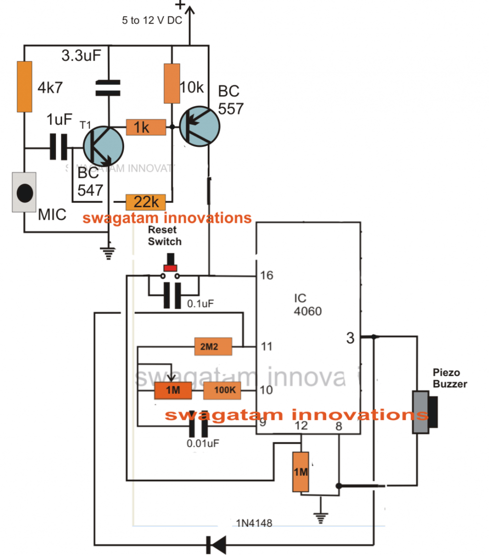
As can be seen the given circuit diagram, it basically consists of two stages, the upper transistor latch stage, and the lower IC 4060 timer stage.

Initially when power is switched ON the IC 4060 circuit is held switched OFF since the BC557 transistor is unable to conduct.The two transistors BC547 and BC557 are configured in the form of a simple latch circuit.

The MIC is placed such that it is able to sense the vibrations of the poultry feed mechanism as soon as it activates.

When the vibrations are picked, the MIC allows  an instantaneous pulse to enter the BC547 transistor activating it for a fraction of a second.

The above conduction of the BC547 in turn activates the BC557 latching the stage via the feedback resistor from the collector of BC557 to the base of BC547.

Once latched the IC is allowed to receive the required supply voltage for its operations.

The IC immediately starts counting and after a predetermined time period set by the 1M pot, pin#3 of the IC becomes high which latches the IC via the diode to pin#11.

The process actuates the connected buzzer which begins alarming regarding the lapsed time.

The circuit can be reset for repeating the cycle by switching OFF the power and switching it back ON.

In case only the IC is required to be reset, the given "reset switch" may be utilized.

Circuit Diagram

poultryfeedcontrollercircuit

You'll also like:

  • 1.  Arduino 2-Step Programmable Timer Circuit
  • 2.  Simple Programmable Timer Circuit
  • 3.  Timer Based Cell Phone Charger Circuit
  • 4.  Simple Digital Timer Circuit with 2 Digit Display
  • 5.  Timer Controlled Submersible Pumpset Circuit
  • 6.  Timer Controlled Exhaust Fan Circuit

About Swagatam

I am an electronics engineer with over 15 years of hands-on experience. I am passionate about inventing, designing electronic circuits and PCBs, and helping hobbyists bring their projects to life. That is why I founded homemade-circuits.com, a website where I share innovative circuit ideas and tutorials. Have a circuit related question? Leave a comment.... I guarantee a reply!

Previous Post: « Non-Contact Cable Tracer Circuit
Next Post: Programmable Bidirectional Motor Timer Circuit »

Reader Interactions

Comments

  1. kristin says

    November 25, 2014 at 1:14 pm

    here is the information of the timer.•Ratings: 120 Volt, 60-hertz / 15 Amp, 1800-Watt resistive / 8.3 Amp, 1000-Watt tungsten / 8.3 Amp, 1000 VA ballast

    SPECIFICATIONS

    Amperage (amps) 15 Assembled , Type Timer

    Timer Type In-Wall Voltage (volts) 120
    Wall Plate Included No Wattage (watts) 1800

    Reply
    • Swagatam says

      November 26, 2014 at 10:49 am

      it looks like a mechanical type of timer, in that case I am afraid you won't be able to modify it for a DC low voltage operation.

      Reply
  2. kristin says

    November 24, 2014 at 4:25 pm

    Hi Swagtam,

    I have timer relay which works with 120v ac I want it to work for 12-24 v dc. how can I convert it from ac to dc? I don't have much knowledge but from circuit I can do that so can you please help me?

    Reply
    • Swagatam says

      November 25, 2014 at 7:41 am

      Hi Kristin,

      If it's an electronic relay circuit then you can open it and locate the (+)(-) rails of the circuit and feed the external 12V to these rails, however before this you should check the operating voltage of the circuit by checking the associated relay coil voltage

      Reply

Need Help? Please Leave a Comment! We value your input—Kindly keep it relevant to the above topic! Cancel reply

Your email address will not be published. Required fields are marked *

Primary Sidebar

Subscribe to New Circuit Ideas

Categories

  • Arduino Projects (87)
  • Audio and Amplifier Projects (132)
  • Automation Projects (17)
  • Automobile Electronics (101)
  • Battery Charger Circuits (83)
  • Datasheets and Components (104)
  • Electronics Theory (143)
  • Free Energy (37)
  • Games and Sports Projects (11)
  • Grid and 3-Phase (19)
  • Health related Projects (25)
  • Home Electrical Circuits (12)
  • Indicator Circuits (14)
  • Inverter Circuits (87)
  • Lamps and Lights (142)
  • Meters and Testers (69)
  • Mini Projects (46)
  • Motor Controller (64)
  • Oscillator Circuits (27)
  • Pets and Pests (15)
  • Power Supply Circuits (108)
  • Remote Control Circuits (50)
  • Security and Alarm (64)
  • Sensors and Detectors (101)
  • Solar Controller Circuits (59)
  • Temperature Controllers (42)
  • Timer and Delay Relay (49)
  • Transmitter Circuits (29)
  • Voltage Control and Protection (37)
  • Water Controller (36)

Calculators

  • Battery Back up Time Calculator
  • Capacitance Reactance Calculator
  • IC 555 Astable Calculator
  • IC 555 Monostable Calculator
  • Inductance Calculator
  • LC Resonance Calculator
  • LM317, LM338, LM396 Calculator
  • Ohm’s Law Calculator
  • Phase Angle Phase Shift Calculator
  • Power Factor (PF) Calculator
  • Reactance Calculator
  • Transistor Astable Calculator
  • Transistor base Resistor Calculator
  • Voltage Divider Calculator
  • Wire Current Calculator
  • Zener Diode Calculator
  • Filter Capacitor Calculator
  • Buck Converter Calculator
  • Boost Converter Calculator
  • Solar Panel, Inverter, Battery Calculator
  • Wire Current Calculator
  • SMPS Transformer Calculator
  • IC SG3525, SG3524 Calculator
  • Inverter LC Filter Calculator

People Also Search

555 Circuits | 741 Circuits | LM324 Circuits | LM338 Circuits | 4017 Circuits | Ultrasonic Projects | SMPS Projects | Christmas Projects | MOSFETs | Radio Circuits | Laser Circuits | PIR Projects |

Recent Comments

  • Swagatam on SG3525 Full Bridge Inverter Circuit
  • Swagatam on Timer Based Cell Phone Charger Circuit
  • Swurvz on SG3525 Full Bridge Inverter Circuit
  • Nitesh Agrawal on Timer Based Cell Phone Charger Circuit
  • Swagatam on Real MPPT Solar Charger Circuit Using Arduino, LCD, and Manual/Auto Switch

Company

  • Privacy Policy
  • Cookie Policy
  • About Me
  • Contact
  • Disclaimer
  • Copyright
  • Videos
  • Sitemap

Social Profiles

  • Twitter
  • YouTube
  • Instagram
  • Pinterest
  • My Facebook-Page
  • Quora
  • Stack Exchange
  • Linkedin
  • © 2025 · Swagatam Innovations