• Skip to main content
  • Skip to primary sidebar

Homemade Circuit Projects

Need circuit help? Post them in the comments! I've answered over 50,000!

Blog | Categories | About | Contact | Calculators-online
You are here: Home / Motor Controller / Greenhouse Motorized Water Diverter and Humidity Controller Circuit

Greenhouse Motorized Water Diverter and Humidity Controller Circuit

Last Updated on March 13, 2019 by Swagatam 2 Comments

In one of the previous posts I have explained the making of a greenhouse temperature controller circuit, here we study how the effects may be enhanced through an automatic water valve actuator and humidity controller circuits. The idea was originally requested by Mr. Leandros Komninos

Table of Contents
  • Technical Specifications
  • The Design
  • Temperature Sensor Circuit Diagram
  • Humidity Sensor Circuit

Technical Specifications

Found one on ebay, these are the detail tehy supply:

1 x RS-360SH Pumping motor
Simple gear-type pumping model, usually used for aquarium, DIY model etcs
Diameter: 2.7 cm
Length: 5.2 cm
Out of the water hole diameter: 4 mm
Rated voltage: 7.2V
Suitable for voltage: 3v-12v DC (marked with a red dot that Terminal is positive)

Seems ideal, but what do you think?. Still looking for a valve system, don't know where to begin!?!? i guess miniature butterfly actuators would be overkill for this.

Oh, here's an additional thought for this setup; can there be an additional set of temp/humidity sensors, and another pump setup as a spray. this would keep the humidity inside the greenhouse ideal. This seems like a setup that might be worth you patenting!

The Design

The requested two designs may be understood with the help of the following discussion:

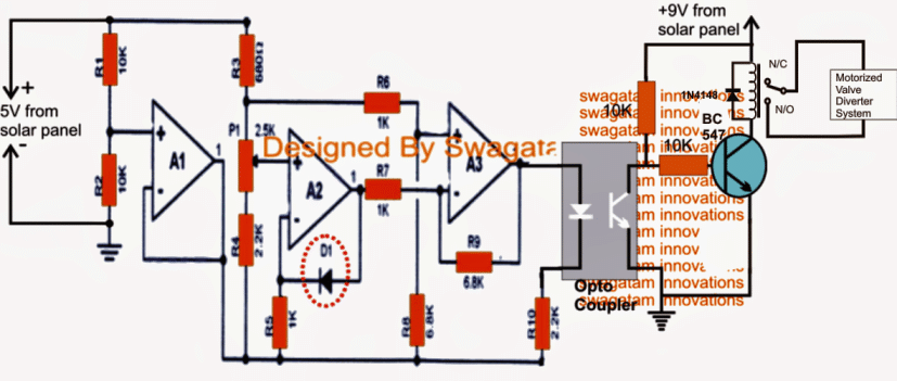
Referring to the first circuit diagram below which is basically wired as a temperature sensor, is enhanced with a relay stage for automatically switching a motorized valve system or actuator which diverts cold water into the greenhouse water supply pipes in an event when the water temperature tends to rise above a predetermined set level.

Temperature Sensor Circuit Diagram

warning message: electricity is dangerous, proceed with caution
valve motor operator circuit 1

This circuit is quite identical to the one that's explained in one of the previous articles, for a comprehensive study regarding the circuit details, you could refer to the following article:

Greenhouse temperature regulator

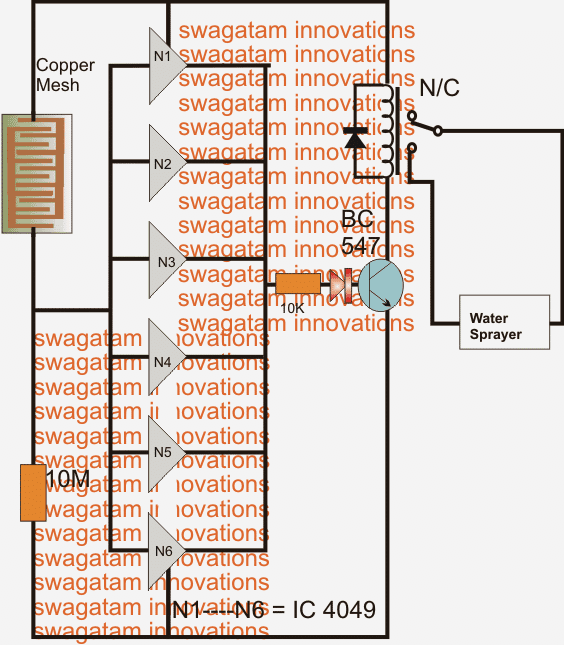
The following design is a simple humidity sensor circuit which could be applied for sensing and controlling greenhouse humidity levels.

As may be seen in the diagram, six NOT gates are connected in parallel for obtaining maximum effectiveness from the devices.

The gates are all positioned as potential difference sensors across their input pins.

The 10M resistor initially holds the inputs to a low logic level since it's connected with the ground supply of the circuit.

The inputs are also terminated to the positive through an appropriately etched PCB to form a closely configured copper mesh layout.

As long as the humidity level is not beyond the undesired threshold, the NOT gates inputs continue to be at a low logic state resulting a high at their outputs which keeps the relay and a connected water sprayer activated.

However, the moment the humidity level tends to cross the set high level it tends to develop a low resistance across the copper mesh PCB forcing the inputs of the NOT gates to become higher in potential until it flips and inverts the individual outputs to logic low, which in turn switches OFF the relay and the water sprayer for the time being.

The 10M resistance may be tweaked for setting-up the desired cut off humidity threshold level.

The LED ON indicates the toggling of the relay and vice versa

Humidity Sensor Circuit

green house auto water sprayer circuit 1


You'll also like:

  • 1.  High Voltage DC Motor Speed Regulator Circuit
  • 2.  Motor Protection Circuits – Over Voltage, Over Heat, Over Current
  • 3.  Climate Dependent Automatic Fan Speed Controller Circuit
  • 4.  50V 3-Phase BLDC Motor Driver
  • 5.  Wireless Servo Motor Control Using 2.4 GHz communication link
  • 6.  Wireless DC Motor Speed Control Circuit

About Swagatam

I am an electronics engineer with over 15 years of hands-on experience. I am passionate about inventing, designing electronic circuits and PCBs, and helping hobbyists bring their projects to life. That is why I founded homemade-circuits.com, a website where I share innovative circuit ideas and tutorials. Have a circuit related question? Leave a comment.... I guarantee a reply!

Previous Post: « Capacitor Based LED Tubelight Using 1 Watt LEDs
Next Post: Parallel Battery Charger Circuits Explained »

Reader Interactions

Comments

  1. Imran yousaf says

    October 3, 2017 at 3:28 pm

    Dear sir,
    I hope your fine and you give me better suggesting for my project
    I am really glade to study this side is verry good for Lerner such as me
    I want to used this circuit for egg encobetr humidity control and temperature is it possible?
    My requirements is like that I want to make such project which includes
    LED display for temperature and humidity
    I want to run one heater for humidity when the humidity reached exec set point the heater will off and then blew the set point heater will on
    Same as for temperature I need spread two Pont for controlling humidity and temperature on one card
    Sir also need to display temprature and humidity Lcd
    I hope you understand my requirements and you give me better solution

    Reply
    • Swagatam says

      October 4, 2017 at 1:08 am

      Imran, for accurate results you can try a Arduino based circuits as explained here:

      https://www.homemade-circuits.com/?s=temperature+humidity

      Reply

Need Help? Please Leave a Comment! We value your input—Kindly keep it relevant to the above topic! Cancel reply

Your email address will not be published. Required fields are marked *

Primary Sidebar

Subscribe to New Circuit Ideas

Categories

  • Arduino Projects (87)
  • Audio and Amplifier Projects (132)
  • Automation Projects (17)
  • Automobile Electronics (101)
  • Battery Charger Circuits (83)
  • Datasheets and Components (104)
  • Electronics Theory (143)
  • Free Energy (37)
  • Games and Sports Projects (11)
  • Grid and 3-Phase (19)
  • Health related Projects (25)
  • Home Electrical Circuits (12)
  • Indicator Circuits (14)
  • Inverter Circuits (87)
  • Lamps and Lights (142)
  • Meters and Testers (69)
  • Mini Projects (46)
  • Motor Controller (64)
  • Oscillator Circuits (27)
  • Pets and Pests (15)
  • Power Supply Circuits (108)
  • Remote Control Circuits (50)
  • Security and Alarm (64)
  • Sensors and Detectors (101)
  • Solar Controller Circuits (59)
  • Temperature Controllers (42)
  • Timer and Delay Relay (49)
  • Transmitter Circuits (29)
  • Voltage Control and Protection (37)
  • Water Controller (36)

Calculators

  • Battery Back up Time Calculator
  • Capacitance Reactance Calculator
  • IC 555 Astable Calculator
  • IC 555 Monostable Calculator
  • Inductance Calculator
  • LC Resonance Calculator
  • LM317, LM338, LM396 Calculator
  • Ohm’s Law Calculator
  • Phase Angle Phase Shift Calculator
  • Power Factor (PF) Calculator
  • Reactance Calculator
  • Transistor Astable Calculator
  • Transistor base Resistor Calculator
  • Voltage Divider Calculator
  • Wire Current Calculator
  • Zener Diode Calculator
  • Filter Capacitor Calculator
  • Buck Converter Calculator
  • Boost Converter Calculator
  • Solar Panel, Inverter, Battery Calculator
  • Wire Current Calculator
  • SMPS Transformer Calculator
  • IC SG3525, SG3524 Calculator
  • Inverter LC Filter Calculator

People Also Search

555 Circuits | 741 Circuits | LM324 Circuits | LM338 Circuits | 4017 Circuits | Ultrasonic Projects | SMPS Projects | Christmas Projects | MOSFETs | Radio Circuits | Laser Circuits | PIR Projects |

Recent Comments

  • Swagatam on Adjustable 0-100V 50 Amp SMPS Circuit
  • ibrahim on Adjustable 0-100V 50 Amp SMPS Circuit
  • Swagatam on Contact
  • KRAB Babu on Contact
  • Swagatam on How Shunt Regulator TL431 Works, Datasheet, Application

Company

  • Privacy Policy
  • Cookie Policy
  • About Me
  • Contact
  • Disclaimer
  • Copyright
  • Videos
  • Sitemap

Social Profiles

  • Twitter
  • YouTube
  • Instagram
  • Pinterest
  • My Facebook-Page
  • Quora
  • Stack Exchange
  • Linkedin
  • © 2025 · Swagatam Innovations