In this post I have explained a circuit that will switch off a group of lamps in sequence with a predetermined delay rate, as set by the user through a built in pot. The ideas was requested by Mr. Azam Jamal
Technical Specifications
I want to make a circuit which works like: I have 9nos 25 watt CFL bulbs and I want that when I switch off the first bulb then after each 5 minutes the remaining light would switch off regularly like each should go off after 5 minutes of other means that in 45 minutes all 9 lights go off respectively. Please help me ?
The Design
The circuit functioning can be understood as follows:
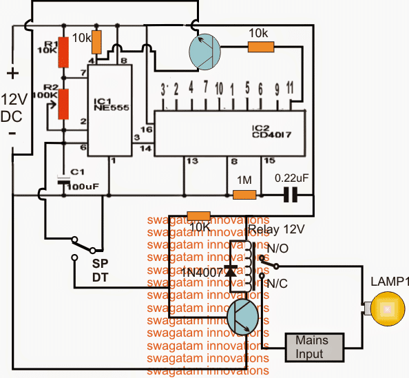
The first circuit below which is a simple IC 555 and IC 4017 lamp chaser produces the basic sequencing of the lamps at the rate of 5 minutes, the time frequency being determined by the 100k pot setting.
It must be set to produce a frequency that may be 50% of the desired sequencing rate, meaning here it must be set to produce the ON and OFf periods at the rate of 2.5 minutes.
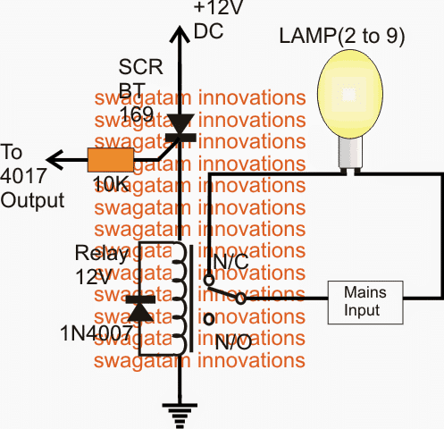
The second circuit is a simple a SCR based relay driver circuit which needs to be repeated 9 times across the intended outputs of the 4017 IC.
As per the request as long as the SPDT is toggled toward the ground position, the IC555 stays disabled and the first lamp(1) is held switched ON indefinitely.
Also in this position, all pinouts of the IC 4017 from pin2 onwards is locked at zero voltage, which means that the connected SCR relay drivers have their relays in their N/C positions making sure that all the connected lamps stay switched ON.
So all the nine lamps from pin2 to pin11 of the IC 4017 is now in an activated position along with lamp1 associated with the SPDT transistor relay driver stage.
At the desired period when the SPDT is toggled, the first lamp(1) is switched OFF and the 555 timer circuit is initiated with its counting process.
After 5 minutes the 555 IC inputs its first legit pulse to pin14 of the 4017 making pin2 to go high which in turn latches the relevant SCR relay driver switching off the first lamp in the sequence.
After another 5 minutes pin4 goes high switching OFF the associated SCR relay driver lamp, and the process repeats until the last pin11 in the sequence gets activated, switching off the last lamp in the sequence, and this also locks pin4 of the IC555 freezing the whole circuit until the operations are reset by the user for restarting the cycle afresh.
Circuit Diagram
The Relay Driver Stage


Questions & Answers
This I like. I’d be very interested into a circuit that is somewhat a “mirror” of this meaning, Light one comes on and stays on then the next one comes on and like the first it stays on. This would continue until all the lights are lit then they would all go off and start over again. Am I making sense? This effect is used on some airport runway lighting to let us pilots know where the runway is, which one to use and the direction of landing. Simply follow the lights.
Yes, that is definitely possible. To accomplish that you just have to eliminate the SPDT switch and the associated transistor relay driver stage, and use the remaining circuit to fulfill your requirement.
Hi Swagatam,
Thank you for your reply.
I am sorry to bother you again, but I have no clue how to hold more outputs high. I have tried to study other circuits using a 4060 IC, but they are mostly timer circuits and only with 1 output high at a time.
What I would like to achieve after connecting the circuit to 12V DC.
The circuit should turn on the outputs randomly where more outputs could stay high for a time period and then turn off. When the circuit has completed all outputs it should do a reset to start all over.
Would you be so kind to help me out here? I would be very grateful for your help.
Thank you in advance.
I will send you the question from Hangout to your email.
Hi Henrik,
You can use pin1/2/3 of the IC for achieving simultaneous switch ON of the loads for some period of time, for example, if pin3 is set to be ON for 8minutes, pin2 will be ON for 4minutes and pin1 for 2 minutes…meaning for 2minutes all the three lamps across these outputs will ON together, or for 4 minutes at least 2 lamps will be ON….if you use other subsequent pins, then you may get at least 5 lamps simultaneously ON for at least 1mnute or 6 lamps ON for at least 30 seconds and so on….
Hi Swagatam,
Thank you very much for your reply.
I am fairly new in building electronics so please forgive me if I ask stupid questions.
Is it possible to hold more outputs high on the 4060 IC at the same time?
If not could I with a transistor relay driver hold it high with a capacitor?
I want to connect LED’s to the outputs and have more of them lit at the same time in random order.
I see that pin 7 is the first output and pin 5 the second and that output 5 generates exact the double time period of pin 7 from your Simple Timer Circuit Using IC 4060.
Does that mean if output 7 is held high for 1 second. Output 5 is held high for 2 seconds or is it the time period before the output goes high?
By the way did you get my question about detecting a model train locomotive? I was so foolish to ask you through Google Hangout which I never use. Can I post my question here or by email?
Again thank you very much for helping us newbies.
Hi Henrik,
Yes it's possible to get a high on several pins at a time, and yes it's also correct that from pin7 onwards upto pin3 sequentially generate a 2X time interval that is twice the time interval of the preceding one or 1/2 the frequency of the previous pinout.
I did not yet see your question in the hangout if possible I'll check it out.
Hi Swagatam,
Thank you very much for all your great schematics and explanations.
Your circuit Switching OFF Lights in a Periodic Sequence makes me think that maybe a modified version of this circuit could help me producing a living house circuit.
I would like a circuit that turns on / off outputs in a random order. Simulating a living house or an office building where the light goes on/off in different rooms. Each output in random order if possible. Eg. Room 1 could stay on while 2 turns off etc.
The circuit is for my model railroad track.
The circuit should auto reset when all outputs has been raised.
I hope you can understand what I mean.
Thank you very much in advance,
Henrik Lauridsen, Denmark
Hi Henrik, thanks,
There's even a simpler alternative of implementing the required application..
You can use a 4060 timer IC in its standard form and out of its 10 outputs select the desired ones as per your liking and configure these with a transistor relay driver stage.
The selected outputs will provide a random set of ON/OFF switching to the connected lamps.
you can vary the timing of the lamp ON/OFF through a pot and also try other outputs for varying the randomness of the switching.
You can find plenty of simple 4060 timer circuits online, or even through this blog.