In this post I have explained a smart mains fire hazard protector circuit which can be used for preventing mains grid transformers from over heating and causing sparks or even burning due to a possible fire. The idea was requested by Mr. Ravindra Shedge
Technical Specifications
I am Ravindra Shedge from Mumbai.
I am looking for a circuit or device which can detect sparks at transformers. or early detection system which can alarm before the transformer blows.
please suggest some measure, how it can be done.Regards,
Ravindra Shedge.
The Design
A transformer would tend to catch fire or cause sparks if the load connected with it exceeds its maximum tolerable wattage rating.
However before the malfunction is able to initiate, the transformer would probably first heat up to drastic levels causing a possible fire or sparks across the winding.
The proposed transformer fire hazard protector circuit is designed to monitor both of these issues, and switch off the system in case any of these critical conditions can cross the danger threshold.
Let's try to understand how the circuit is intended to operate for the preventing a possible fire inside a transformer.
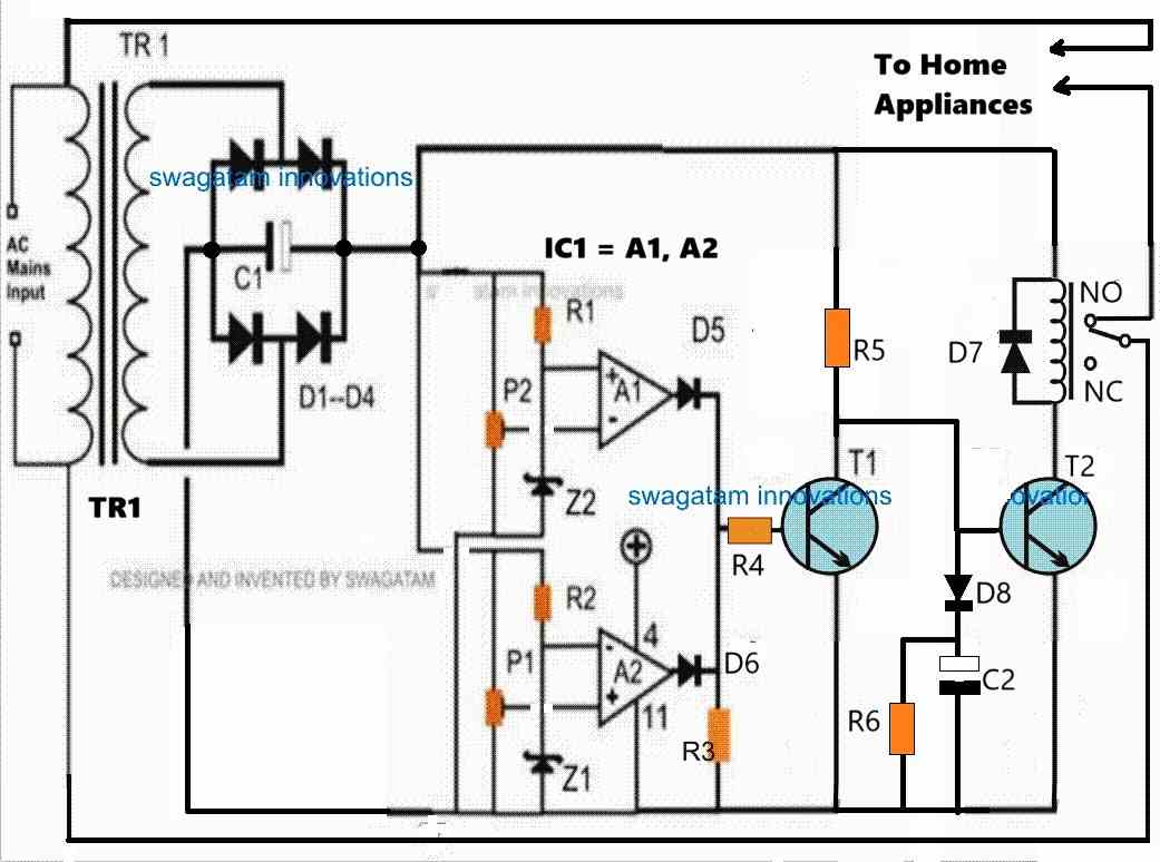
Referring to the circuit diagram, we see the configuration consisting of three stages, a heat sensor stage consisting the BJT BC547 as the sensing element, a threshold detector stage made around the opamp IC 741 and a current sensing wired around Rx and the connected bridge network using D7---D10.
As discussed above, a transformer would get too hot before any sort of fire hazard, the heat sensor in the circuit is positioned to tackle this issue before it gets too late.
Transistor T1 along with D5, R1, R2, VR1 and OP1 form the heat sensor stage, the circuit functioning may be learned in detaul HERE.
Making LDR/LED OPtocoupler
OP1 is a hand made opto coupler wherein two 5mm red LEDs are sealed along with a tiny LDR face to face inside a light proof enclosure, an example unit using a single LED may be studied in this article.
For the present application two LEDs will need to be enclosed with one LDR inside the opto module.
VR1 is set in such a way that when the heat around BC547 exceeds 90 degrees Celsius, the left hand side LED inside OP1 begins illuminating.
The above illumination of the left hand side LED inside the opto lowers the LDR resistance which causes pin2 of the opamp to become just higher than its pin3 reference voltage.
As soon as the above situation occurs opamp output flips to a low logic from its initial high logic state, switching ON the relay.
The relay contacts which are wired in series with the transformer mains input instantly switches OFF the transformer preventing any further heating up of the system and a possible fire hazard.
The right hand side LED inside the opto is positioned for detecting an overload or an over current situation within the transformer.
In case of an over load, the resulting increased amp level induces a potential rise across the sensing resistor Rx which in turn is translated into a DC for illuminating the right hand side LED of the opto.
Quite identically this condition too lowers the LDR resistance causing a higher potential to develop at pin2 of the opamp than its pin3 forcing the relay to actuate and cut off the supply to the transformer stopping all chances of a possible spark or burning inside the transformer.
Calculating Current Limit
Rx may be calculated using the following formula:
Rx = LED forward drop/maximum amp threshold = 1.2/Amp
Suppose the maximum tolerable amp which should not exceed the output is 30amps, Rx could be figured as:
Rx = 1.2/30 = 0.04 ohms
wattage of the resistor would be 1.2 x 30 = 36 watts
Circuit Diagram
![]()
Note: T1 must be positioned as close as possible to the transformer, while D5 must be kept exposed to ambient atmosphere, well aloof from the transformer heat.
Parts List
R1 = 2k7,
R2, R5, R6 = 1K
R3 = 100K,
R4 = 1M
D1---D4, D6, D7---D10 = 1N4007,
D5 = 1N4148,
VR1 = 200 Ohms, 1Watt, Potentimeter
C1 = 1000uF/25V,
T1 = BC547,
T2 = 2N2907,
IC = 741,
OPTO = LED/LDR Combo (see text).
Relay = 12 V, SPDT. amp spec as per transformer rating


Need Help? Please Leave a Comment! We value your input—Kindly keep it relevant to the above topic!