In this post I have explained a self locking worm gear mechanism for hoisting heavy loads through an electrical motor. The main feature of the system being its self locking in an event of a motor failure. The idea was requested by Mr. Amit Patkar.
Technical Specifications
I love electronics, especially automation, I have been making things using kits from lamington road. but since I have no formal education or background in electronics/ engineering, I get stuck.
I love automation may be because I am lazy but I keep getting ideas. While searching for some design that would fit my need on web and thankfully, I landed on your page. I hope you can suggest me some good idea.
We stay on the third floor of a old design building, with no lift. If I keep my Cycle and my kids cycles on the ground floor, they are prone to be stolen, and I have back pain and its difficult to carry cycles 3 floors every time anyone of us need to ride. Also it consumes carpet area of the house.
Requirement
I have a strong Grill where a Pulley mechanism can be fixed. which can be operated using remote.
1) Horizontal movement of rod to put the Pulley 3 ft Away from the Building structure to avoid damage to any window sheds.
2) Vertical movement only on press of remote button. Stop when button released. This will avoid accidental crashing.
3) Rubber based Pick up, can put a rubber jacket on hooks. To avoid damaging the paint.
4) When Vertically pulled up, and horizontally back. It can be set on additional manual hooks, to avoid pressure on the pulley.
5) if Some kind of base is made, it can be used to carry things purchased from Dmart. HaHa.
let me know your views.
Thanks
Amit Ramakant Patkar.
Navi Mumbai.
The Design
The requested idea looks more mechanical by nature than electronic, so it becomes imperative to discuss the mechanical part elaborately first.
The proposed remote controlled bicycle hoist mechanism needs one very important feature to be included in the system, which is obviously necessary for most pulley based hoist mechanisms, it's the self locking feature to prevent reverse unrolling of the pulley in an event of a motor failure.
Employing a Worm Gear Mechanism
A very effective way of implementing the self locking feature is by employing a worm gear system, as may be witnessed in the image below.
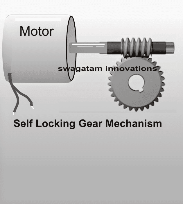
Here we see a horizontal spiral drill bit shaped shaft with its teeth locked within the teeth of a normal circular gear wheel.
Now, as the spiral gear is rotated through a motor its teeth tend to push and roll in the forward motion pushing the teeth of the circular gear in the same direction resulting in a synchronized rotation of the lower circular gear.
The circular gear is the one which is used for lifting or moving the load and in case the motor fails due to power failure or any other malfunction, the spiral gear makes sure that the circular gear teeth get locked across the spiral gear teeth and becomes almost motionless under such situations.
This principle is what makes a worm gear system most desirable for the proposed bicycle hoist mechanism.
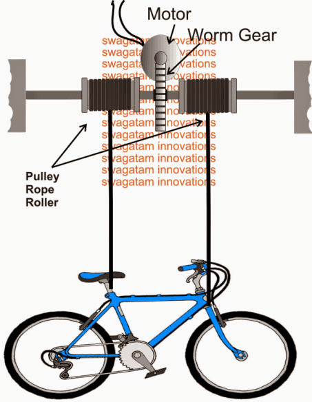
The following diagram shows the method in which the above explained worm gear mechanism could be implemented in between parallel supports and with the help of two adjacent rope and pulley assembly.
As per a visual simulation it may be witnessed that when the motor is actuated, the gear assembly starts moving in a certain predetermined direction such that the load is pulled upwards through coiling of the rope around the two adjacent pulleys, the reverse happens when the motor direction is flipped.
The central rod which could be seen supported (pivoted) over firm structures on either side must be enhanced with sealed ball bearing rings in order to facilitate a smooth rotation of the whole system.
How to Use RF Remote Control for the Mechanism
The above discussion explained how the pulley hoist mechanism needs to be fixed, next, as per the request the motor is intended to be controlled via a remote control circuit.
Nowadays RF remote modules could be procured pretty cheaply and easily from the local electronic shops, so it's recommended to buy one instead of trying to make one.
You can read more about it in this POST
For hard core enthusiasts who would like to build everything with their own hands, a related circuit design is discussed in this POST
In case you have procured ready Rx, Tx modules, you will find the receiver Rx units of these RF modules having integrated relays however these relays could be quite inferior with their load handling capacity and therefore should be reinforced with external relays, especially when the load is a high current type like in the present application.
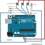
Preferably buy a two-relay RF module because we need just two relays for controlling the reverse forward motions of the motor. A classic example of a two relay module may be seen in the following image.
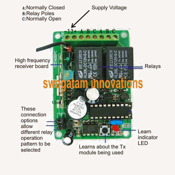
Receiver Rx Module
Transmitter Tx handset Module
The enclosed relays in the Rx PCB will operate in response to the pressing of the corresponding buttons on the Tx transmitter module, so it's all about tracing out the N/O, N/C and the poles of these two relays and wire them up with the external heavy duty relays for enforcing the desired motor reverse forward motions.
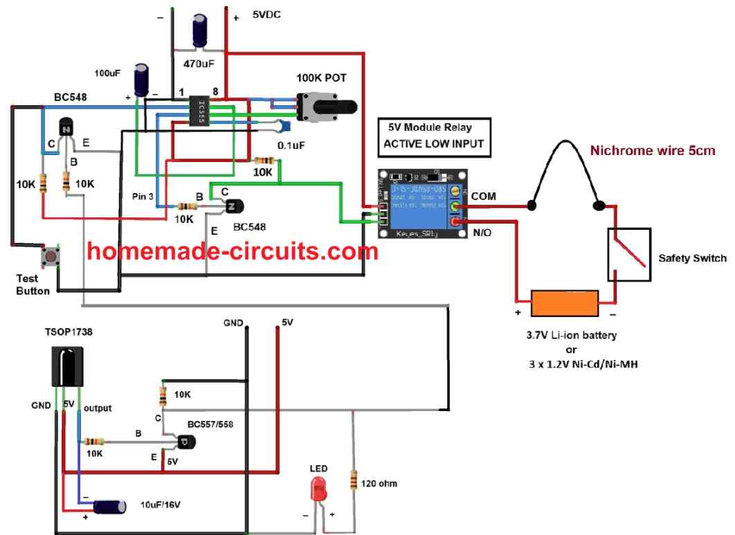
The following diagram comprehensively details the wiring layout of the relays, once the wiring is completed as per the shown diagram one of the buttons will cause the motor to rotate clockwise while pressing the other would flip the motor direction anticlockwise.
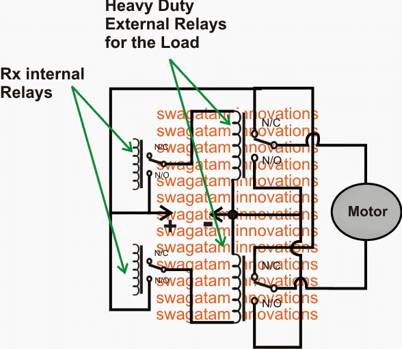
When no buttons are operational the motor would stationery. The motor would wind or unwind the pulley ropes for as long as the relevant buttons of the Tx is held pressed by the user and would halt once released.
Alternatively, you could try playing with the in-built Rx modules "relay operation selector" connections by inserting the plugs appropriately until the required spec is found wherein the relay is allowed to toggle ON/OFF with every alternate press of the Tx buttons and the user don't have to keep the relevant Tx button pressed continuously for executing the intended motor rotations.


Questions & Answers
Hi, I looked at your system & liked it. But I am looking at cheap & cost effective solution ( No gears) Here is my request with simple requirements:
1) Simple plastic single pulley , which can roll about 30 M of thin rope length.
2) Can pull Max load of 20 kilos & pulley can be mounted on the wall.
3) Remote control pulley with up & down movement. ( Hand held battery/electric remote control)
Let me know what is the cost estimate & if you can make a prototype.
4) All system should be of strong plastic to avoid high cost & weight.
Thanks
Hi, you can use the same concept which is explained, just remove the shown gear mechanism and replace the motor shaft with an ordinary pulley mechanism.
Sorry, I cannot build the prototype.
Hi I want a pulley to fit into the back of a skoda estate car that will pull a mobility scooter up the ramps
Have you any advice or ideas
Many thanks
Jim
Hi, I want more details on the set up, only then I can figure out the system.