The article comprehensively discusses a MPPT based smart solar cell phone charger circuit. The idea was requested by one of the avid readers of this blog.
Technical Specifications
I am an electric and electronics final year student. My final year project title is smart solar charger for cellular phones. i was hoping sir can help me on how to make a solar charger smart.
Something i came across was using user interface such as use led to inform the user whether the solar radiation is enough to charge the charger or something like that. But i am not sure about how the circuit will look like and what components are needed. Hoping for some assistance from sir.
I was thinking about using user interface to make the solar charger 'smart'. With a feature informing the user whether the the amount of sunlight is enough for efficient charging. For example if the light radiation is too low, user will be informed via lighted LED or display screen.
And when the solar charger is fully charged, an LED lights up to inform the user that the solar charger is ready for use.
That is what I have thought about developing so far sir. But i am not sure about the complexity of it therefore i am open to any new suggestion to improve this design.
I have also read some articles on sir's blog regarding mppt. I am not sure whether i should consider adding that into this design as i am not familiar to the complexity of building this circuit.
I am supposed to develop a portable smart solar charger for cellular phones. Therefore i considered using user interface to inform the users as a 'smart' method. Hoping sir can help me with the development of this circuit. I am also open to any new suggestions sir.
Thank you for your quick feedback and I truly appreciate your assistance sir.
Have a great day sir.
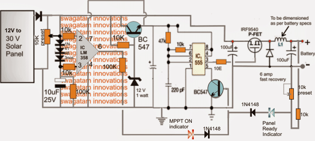
The Design
Referring to the above smart solar charger circuit, the design may be divided into three fundamental stages:
1) The mosfet based buck converter stage.
2) The IC 555 astable stage, and
3) The opamp based solar tracker MPPT stage.
The stages are designed to operate in the following manner:
The buck converter basically comprises of a P-channel mosfet, a fast response diode and an inductor. This stage is included in order to achieve the desired amount of stepped down voltage with maximum efficiency, since loss in the form of heat and other parameters are minimum using a buck topology.
The IC 555 Stage
The IC 555 stage is rigged to generate a frequency for the buck converter mosfet and also as a constant voltage regulator through its control pin5. The BJT at its pin5 grounds and shuts off the buck converter frequency each time it receives a base trigger signal either from the opamp tracker stage or from the feedback set across the buck converter output via the 10k preset.
Coming to the opamp stage, its inputs may be seen configured in such a way that the potential at the inverting input of the IC stays a pinch higher than its non-inverting input due to the presence of the three 1N4148 dropping diodes.
The 10k preset is adjusted such that at peak voltage the sample solar voltage at pin2 is kept just lower than the supply voltage at pin7, this is essential since the input feed should not be higher than the supply voltage of the IC as per the standard rules and specs of the IC.
In the above situation, the output pin6 of the opamp is held at zero potential owing to the shade lower potential of pin3 than pin2.
The MPPT Optimization
Under optimal load conditions, when the load voltage spec is on par with the solar panel voltage rating, the panel automatically works with maximum efficiency and the opamp tracker stays dormant, however in case an unmatched or incompatible overload load is sensed, the panel voltage tends to get pulled down with the load voltage level.
The situation is tracked at pin2 which also experiences a proportionate voltage drop, but the potential at pin3 stays solid and unmoved due to the presence of the 10uF capacitor, until the moment when the pin2 potential tends to go below the 3 diode drop set across pin3. Pin3 now begins witnessing a rising potential than pin2, which instantly renders a high at pin6 of the IC.
The above high at pin6 sends a trigger at the base of the BC547 transistor positioned across pin5 of the IC555. This forces the astable to shut off itself and the buck output, which in turn renders the load ineffective restoring normalcy across the panel and the opamp tracker stage...the cycle keeps switching rapidly, ensuring an optimized voltage for the load as well as an optimized load for the panel so that its voltage never falls below its critical "knee" zone.
The inductor of the converter stage may be built using 22 SWG magnet wire, with around 20 turns over any suitable ferrite core.
The 10k preset may be used for adjusting the buck voltage to the required levels as per the load specifications.
How to Set up the Circuit
Once built, the above explained smart solar charger may be set with the following procedures:
1) Do not connect any load at the output.
2) Apply an external DC (very low current) across the input of the circuit where the panel is intended to be hooked in. This DC should be at a level approximately equal to the selected panel peak voltage specs.
3) Adjust the 10k preset of the opamp such that the potential at pin2 becomes slightly lower than the potential at pin7 of the IC.
4) Next, adjust the other 10k preset such that the output from the buck converter produces a voltage just equal to the intended load voltage rating. If its a cell phone that needs to be charged, the voltage may be set to 5V, for a Li-ion cell it may be set to 4.2V and so on.
4) Finally connect a dummy load which may have operating voltage rating much lower than the input DC but higher current rating than the input DC....and check the overall response from the circuit.
The circuit must produce the following results:
With the pin6 feed connected with pin5 BJT of the IC 555 the DC should not show a drop of more than 2V than its actual magnitude. Meaning if the input DC is 15V, and the load is 6V, the drop across the input DC may be seen not exceeding below 13V.
Conversely with pin6 disconnected this must fall and align in accordance with the load voltage, that is if the DC is 15V and the load is 6V, the input DC may be seen dropping at 6V.
The above results would confirm a correct and an optimal functioning of the proposed smart solar cell phone charger circuit.
The stages must be built, tested, confirmed step-wise, and then integrated together.
Questions & Answers
L’inductance peut être enforme de tore ( filtre EMI en sortie alim a découpage ) ; du fil de litz , ne serait il pas mieux approprié (effet de peau )
Good morning Swag, Always great projects
I’m setting up this project of yours, which delighted me a lot.
Could you please clarify some questions?
1- Can I use diode 1N4148 also on positive panel output?
2- Can I use a! 00uf / 25v electrolytic capacitor connected to the BC547 emitters? (is worthless in design).
3-What would be the input and output working range?
4-What determines the value of 6A for the diode (fast recovery)?
5-If working with a lower amperage can I just change the mosfet model for voltage and current range?
6-In the case of 27 SWG wire, any suggestions how many turns?
I thank you for your help and cordiality.
Thank you Marcelo, however, this project is yet to be tested, and it’s not recommended for new hobbyists.
Instead you could try this:
https://www.homemade-circuits.com/5v-pwm-solar-battery-charger-circuit/
nice post
thankx
Hi sir…. I'm final year student of diploma in EEE…. I want solar based project please give me some suggestion? ??????
Hi Bhavanjee, you can try the following circuit
https://www.homemade-circuits.com/2016/09/solar-pocket-led-light-circuit.html
Hello sir,
I find this circuit interesting to implement. Could you let me know how to choose a suitable inductor L1 for the circuit? Also, if the current rating is small, can we use carbon inductors for implementing the circuits?
Hello LNB,
L1 will need to determined by some experimentation, initially you can begin with a 22SWG 20 turns on a 10mm ferrite rod, and check the output from it, subsequently you can go on reducing the turns for getting the desired output, make sure the 10k preset near the green LED is kept grounded while the above is being implemented.
yes a carbon inductor can be tried if the load is in mA