In this article I have explained the circuit details of a couple of very interesting and sensitive RF signal meters, which can be used for measuring the RF strength of the transmitted waves from the RF source without making any physical contacts with the source.
Simple RF Signal Meter using IC 741
A RF signal meter of this form is very helpful for identifying the radiation qualities of directional beam transceiver aerials. This makes it possible for the person to dimension the antenna correctly to have the best transmitting radiation pattern. An additional aerial must be placed close by from the primary transmitting antenna.
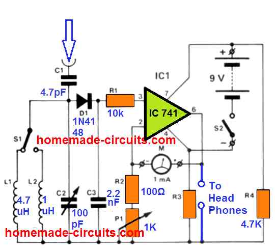
The signal received by the second antenna is subsequently provided to a resonance circuit created by L1, L2 and the varicap C2. This allows the meter to be precisely tuned to the specific transmitting frequency which needs to be measured. With the inductance values shown for the coil in the schematic the 'band width' of the meter can be anywhere between 6 and 60 MHz.
The RF signal after this is applied to the diode D1, consisting of a rectifier/demodulation stage. Lastly the signal is directed to the non-inverting input pin#3 of opamp IC1. The gain of this opamp which decides the sensitivity of the 1 mA meter is fine-tuned by the preset P1.
Performance
The working performance of this RF signal meter circuit was tested to be incredibly sensitive, and tremendously selective. A set of headphones could be attached to the output of the opamp enabling the original RF transmission to be examined. The general resistance of the recommended headphone must not be below 2k2 or else that may call for an additional amplification Stage in the design.
Discussing How to to Build a RF Signal Meter
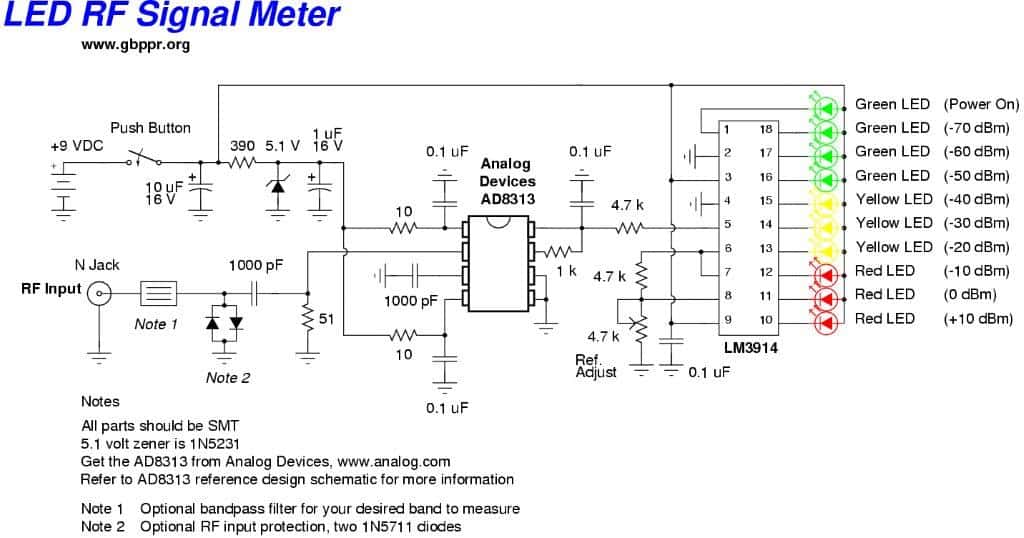
A neat little RF signal meter circuit has been discussed in the following post, which can be used to trace even the minutest RF signals in the ether through an illuminated LED bar graph display. Courtesy: Steven Chiverton.
Hello swagatam busy getting next subject ready for you but here's a circuit from my collection you may like to play around with signals, like it may be useful as another rf ghost detector .
The below given circuit is one of many i collected off the net this one isn't my design bu as years go by many circuits eventually disappear off the net and are then no longer there to build but the idea is if you find something and experiment enough you can improve the old one and or upgrade it.
Using a Gravity Wave Detector Concept
The gravity wave detectors if you still like the details may become handy in the paranormal field as they are on the hodowanec gravity wave detector site but no printed circuits for them and just part of a circuit so ive built them added the amplifier myself and made the printed circuit myself and upgraded them myself and tested them myself and have notes going back a few years
and ive also come up with some of my own using old no longer circuit data say a mic preamplifier you see them on the net but not this one if your not lucky enough to find this exact one anymore i experimented with it and integrated it into my version gravity wave detector that uses a ceramic mic as what you may like to call a ceramic mic ,
its the reader like an areal so the modified mic preamp i used to feed signals to the audio amp ic another one has the 741 as used in the original gravity wave detector and its surrounding few parts but i whacked the modified mic preamp after it in another similar gravity wave detector and so signal gets amplified by the 741 and then fed into the modified mic preamp to amplify it more then to the 386 audio amp is so the amount of changes and upgrades and improvements and modifications using bits of circuits etc is awesome and there's no limit to what you can get ,
so i make printed circuits from old schematics that don't have printed circuit board designs for them and i test and experiment and upgrade and add new ideas to them.


Questions & Answers
Hi, I found the AD8313 version which have very wide bandwidth but need to adjust antenna impedance to match different bandwidth. If I use the 8K ohm (the middle band), how much the gain drops at the high frequency side and the low frequency side ? Or it simplies won’t work.
Thank Mike, may build a board and test.
BR,Francis
Hi, I have not studied the AD8313 IC yet, so I am not sure how it works, so it might be difficult for me to answer your question…
Hello
I am interested in building a tuned rf field strength meter using LEDs and a signal transmitter for the meter to detect. The idea is to place the transmitter in my vehicle and use the field strength to locate the car in a busy parking lot.
Thank You
Mike
Hi, that can be perhaps done, but the field strength meter cannot sense the field from far away distance, you may have to take the unit close to each car for detecting the tuned frequency. Instead of RF you can go for IR or infrared that would be easier to build.
Hello Mr. Swagata
Thank you for the advice and I agree with you that the infrared circuit will be much to build, so I am going to go with the IR circuit instead.
Thank You
Mike
Thanks Mike, sure, you can build an IR based meter for the specified function. Let me know if you have any further questions.
Hi Mr. Swagatam,
Thank you for the advice and I will
Let you know anytime I have any further questions that I need answered.
Thank You
Mike
Sure, no problem!
Hello
I am YO8SZS (Nicu) from Romania and I am interested in building this detector with IC 741. Can you please tell me what is the value of resistor R3 in the diagram?
Thank you very much and congratulations for helping others with your posts.
73de YO8SZS
R3 is also 4.7 K 1/4 watt, I forgot to put this value in the diagram….
Hello
Thanks so much for answering … now I can finish this scheme too.
Respect and respect
YO8SZS Nicu from Romania
Thank you, glad I could help!