The circuit of a 60 watt power amplifier is shown in the below figure. It’s design layout is simple and very conventional. It has a completely symmetrical pattern which has one pole frequency compensation, yet some uncommon methods have been employed in order to keep the number of parts less.
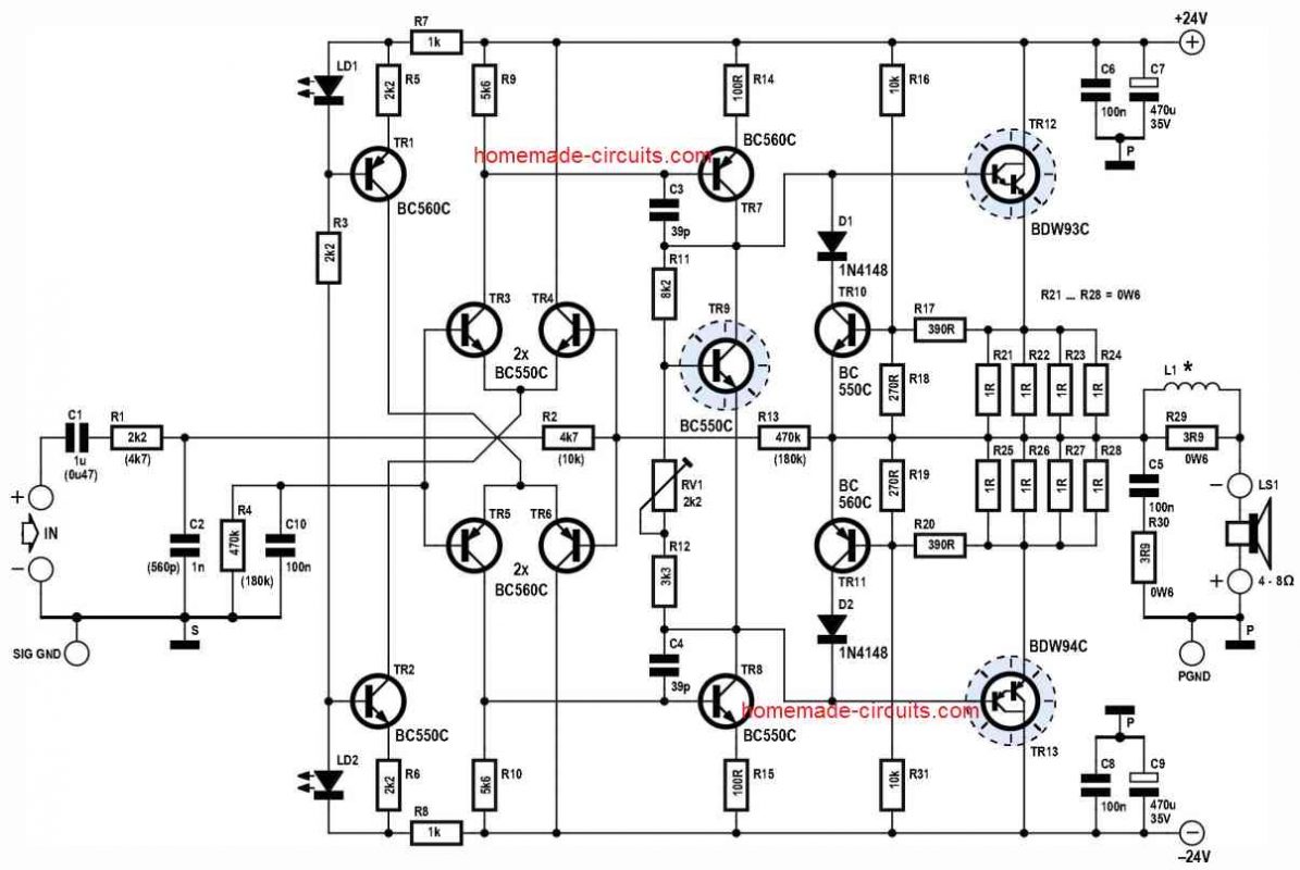
To start with, the configuration of the amplifier is done in the inverting configuration, instead of implementing the common style of a non-inverting layout.
As a result, it is important to connect the speaker with reversed polarity. However inverting amplifiers don't need to perform too much to rectify the open-loop phase shifts, simply like their own non-inverting counterparts which is distinctly an advantage in this straightforward design.
Furthermore, the input capacitor in this design performs a dual function. It delivers AC coupling and also minimizes DC gain to unity. To be precise , all frequency dependence is maintained external to the feedback loop here. Thus the signal stays entirely pre-conditioned through the given passive input network in order to reduce some more number of parts.
The fundamental amplifier design, consequently, works using a high gain for frequencies which may be outside of the normal music frequency range. And you can also find that apart from the 39 pF frequency compensation capacitors along with a few essential decoupling, the amplifier circuit isn't rigged with strange RC networks ’in order to get stability’.
Even with the above discussed parameters, this 60 watt amplifier design includes a hypothetical 40° phase margin, while the stream-lined PCB design helps to keep stray signal influences to a lowest level. This is especially due to a discrete design of the power op-amp.
Almost all assessments for the amplifier had been carried out using partly unshielded test probes within an workshop atmosphere which had a lot of electrical noises. Even in such situation, the amplifier prototype revealed absolutely no tendencies of instability.
In earlier times, the majority of amplifiers were being made with fairly small input sensitivity (1Vrms) for the integration with the line level input sources. If you want to configure this amplifier in this way then you can do so by using the component values that are displayed in parentheses, and this will provide a gain of x12 or 22 dB.
However, the fact is that, in these modern times line-level sources are hardly seen in comparison to the low-level headphone output jacks available in smartphones and tablets.
The 60 watt amplifier circuit discussed here offers a gain of 36 dB (x67) that makes it possible for 100 % power output from all standard contemporary headphone jacks (0.2 Vrms). The damping element is negatively impacted with increased frequencies.
Another great thing is the LED used for biasing of the current source transistors. LEDs are used since these devices produce reduced noise compared to zener diodes, which helps to get rid of a couple of bypass capacitors, which also allows lower thermal drift for the amplifier's power switch ON!
Additionally price is less for this design along with compact and sleek nature can be observed for the emitter resistors of the power transistors, where we can find the regular 1-Q types are connected in parallel, providing an extra advantage by means of smaller inductance compared to traditional wire-wound resistors.
The output power transistors on their own are powered from minimal quiescent current, sacrificing incredibly reduced distortion levels for a number of useful advantages, which includes smaller wasted power and the capacity to operate the output stage using TO-92s without heatsinks.
Performance
Despite of using a very standard sets of transistors, the audio output quality was found to be excellent. When the audio quality tests of this 60 watt amplifier was compared to the contemporary expensive Hi-Fi amplifiers, our design demonstrated some tight bass of the audio, very precise fine detail of the music content and an extremely clean midrange vocal frequencies.
Protection
At the full 60 watts output power or 65 watts with 10% THD, the indicated T0-220 output transistors would be working very hard and therefore decent heatsinking is essential for the output power devices.
Although a overcurrent protection circuitry has not been considered in this design, it is always crucial to protect the amplifier through a couple of 2 Amp fuses connected in series with the two supply lines.
60 Watt Stereo Amplifier using Gainclone Concept
The next design is a gainclone 60 watt stereo amplifier circuit, which is capable of producing an excellent sound quality, through a single IC LM3875.
The IC is manufactured by Texas Instruments and can be expected to produce a good 60 watts of power output on a 8 Ohm speaker.
General Features of the LM3875
- The general features of the IC LM3875 can be understood from the following points:
- Total Harmonic Distortion (THD) less than 0.03% within trhe frequency range of 20Hz to 20kHz and supply range of +/-40V.
- Internal protection from voltage spikes, short circuit, and output overload conditions.
- Low Noise output specifically within 95dB
Circuit Diagrams
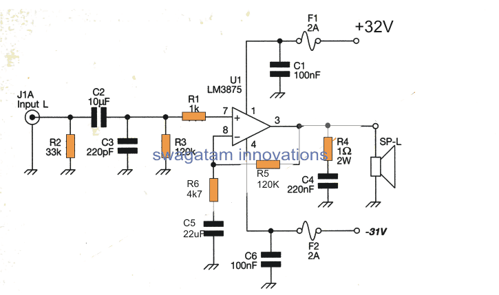
From the figure we can see that the input signal is connected to the resistor R2, which sets the input impedance of the amplifier at 33K along with the coupling capacitor C2.
The input stage comprises of an ultrasonic filter circuit stage made up C3, R3 and R1 which suppresses any entry of noise through a low RF attenuation.
After this the signal is allowed to pass to pin#7 of the IC enabling a 25 times gain for the signal. This gain is sustained by feeding it back to the input pinout via R5 and R6 and is calculated by the formula (1 + R5/R6)
A frequency cut of -3dB below 10Hz is achieved via C5 which may be seen attached with R5.
The amplified music input is delivered from pin#3 which is ultimately fed to the loudspeaker for the amplified sound generation, however before this can happen, the signal has to pass through a network of R4 and C4 which prevents the amplifier from getting unstable during full loads and thus ensures a continuous stable output under full volume.
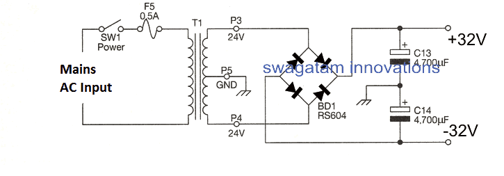
Power Supply
The power supply for this 60 watt stereo amplifier circuit employs a 24-0-24V 5 Amp transformer which is rectified by the indicated bridge rectifier module, and is filtered using C13 and C14.

Questions & Answers
Swagatham you are just outstanding and your blog offer too much to an electronics hobbyist like me. Keep going and I wish you all the best.
Thank you Suresh, I appreciate your kind words! Do Let me know if you have any related questions, I will be happy to help!
About the Variable Resistor, any insight that you could provide about setting the proper value? Many thanks
sir how did you get ×67 gain from that 60w amp
I think it should be actually R13 + R2 / R2 = 470 + 4.7 / 4.7 = 101
The variable resistor is for setting the quiescent current or the idle current for the amplifier. Keep the music input terminals short circuited. Now attach a ammeter (in the milliampere range) in series with the +24V supply. Next, adjust the preset or the variable resistor until you see around 50 mA current on the meter. Confirm the process for the -24V supply line also. That’s all, the quiescent current for the amplifier is set. You can remove the input short circuit now.
And so sorry to bother you once again: If one wanted to raise Input Voltage. Would it be possible, say +-35V? Or should I need to replace key values of passive components? Apart from rated voltage
Sorry i did not understand what to meant by “raising input voltage”? Do you mean using higher voltage for the input music level?
By the way the circuit will support upto +/-35V and produce a higher output power.
Thank you so much. that’s exactly what I wanted to know: If the circuit would be ok with higher voltage: So this means I can apply +-35V. Thanks
Yes +/-35V supply can be used and will produce a proportionately increased power output.
But initially verify the circuit with a 24V DC.
Thanks for the very vast reply. Impressive…
Just to make sure: Values in parentheses, are for 12x Gain, right?
And overall, any modifications you may see fit?
You are Welcome. That’s right, Values in parentheses, are for 12x Gain.
It is a professional design, no further modifications are required.
How good is this amplifier in terms of performance and THD?
I don’t have the exact specifications, but I can assure you that they are extremely good for the first circuit.
What colour led shoud be?
5mm 20 mA, any color
Hello.
Can this circuit be modified, such that:
a). It is powered from higher rail voltages, and
b). It is equipped with the specific “double-complementary” output transistor stage solution, as can be found in the Bryston 4B-SST ?
… I would envision the specific ‘interface point’ in such a way, that:
a). We use the front part of the “60 Watt Amplifier Circuit” – up to the outputs of the bias generator. From there on, we swap the output circuitry and place the “Bryston 4B-SST” end stage, hooking up to the two points on the bias generator.
Can Do?
Will it work?
Can we expect any incremental sonic benefits from such a move?
Bestt Regards,
Ziggy.
Hi,
I think the first circuit can be powered with higher voltages by suitably modifying the respective biasing resistors.
However, I am not sure about the output stage modification, whether that is possible or not?
Excellent article!
What occurs to me out of this is that there is an interesting application for this with a raspberry pi or similar (could be made even into a single board computer that ONLY does this).
1. Pi Hat that connects to the POE leads on the board.
2. Power over Ethernet with mode sensing (i.e. is it 802.3at, bt, or UPoE? (30W, 60W or 100W))
3. If this could be adapted to take 48VDC in by default, then no step down is required from PoE so can directly drive the amp efficiently.
4. Works like a HiFiBerry in that it takes the audio from the board directly and amplifies it.
5. Has a high efficiency buck converter in it that powers the PI at 5V@5.5A.
Why would this rock?
You could then use this for Home Automation designs with a single CAT6 cable to an inwall low voltage enclosure or as a single gang installation that has hardwired ethernet and full AirPlay/DLNA support. (shairplay). You wouldn’t need anything else than speaker wires going to that box and a ethernet cable. And in 802.3AT you’d get ~20W total power for 10W / channel which is more than enough for most rooms. With 802.3BT++ you’d get about 90W of power for 45W / channel which is more than enough for large rooms in most cases.
Thank you for sharing your valuable feedback! Much appreciated!