This yet another versatile 3-phase driver device in the form of IC L6235 from ST Microelectronics allows you to drive a 50V 3-phase BLDC motor with extreme efficiency.The chip also includes all the required protection features built-in, along with an easy to configure external speed control stage.
How the IC L6235 BLDC Driver Works
The IC L6235 is an embedded DMOS 3-phase motor driver with an integrated over-current protection. Designed with BCD technology, the device embeds the benefits of isolated DMOS power transistors with CMOS, and with bipolar circuits within the same device.
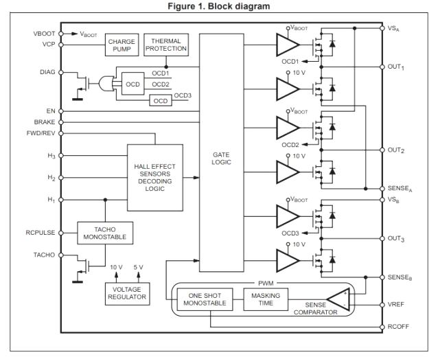
The chips integrates all the circuitry required for effectively driving a 3-phase BLDC motor, as I have explained below:
A 3-phase DMOS bridge, a constant off-time PWM current controller and the decoding logic for single ended hall sensors for generating the essential 120 degree phase shift sequence for the power stage.
With regard to the built-in protections the L6235 device offers a non-dissipative over current protection on the high-side power MOSFETs, protection against ESD, and an automatic thermal shutdown in case the device heats up above the rated value.
50V BLDC Driver Circuit Diagram
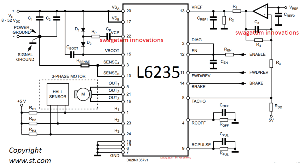
A typical L6235 50V 3-phase BLDC motor driver circuit application can be witnessed above, which looks quite straightforward with its implementation procedures.
You just have to hook up the shown elements in place and use the design to operate any BLDC motor with sensors rated within 8V to 50V at 3 amps rate.
Pinout Details
The pinout function for the specified circuit can be studied from the following data:
Pin#6, 7, 18, 19 = (GND) These are the Ground terminals of the IC.
Pin#8 = (TACHO) It's designated as the open drain output Frequency-to-voltage open drain output. here each single pulse from pin H1 is dimensioned in the form of a fixed and adjustable length pulse.
Pin#9 = (RCPULSE) Is configured like a parallel RC network attached between this pin and the ground, which fixes the period of the monostable pulse responsible for the frequency-to-voltage converter.
Pin#10 = (SENSEB) This pin must be connected together with pin SENSEA to power ground through a sensing power resistor. Here the inverting input of the sense comparator also needs to be connected.
Pin#11 = (FWD/REV) This pinout can be used for changing the rotational direction of the BLDC motor. A HIGH logic level on this pinout will cause a forward motion while, a LOW logic level will allow the BLDc motor to rotate in the opposite reverse direction. For enabling a fixed clockwise or anticlockwise directions, this pinout may be appropriately terminated to a +5V or the ground line..
Pin#12 = (EN) A LOW logic signal will shut OFF all the internal power MOSFETs and stall the BLDC motor. In case this pinout is intended to be not used, it must be terminated to the +5 V supply rail.
Pin#13 = (VREF). You can see an opamp configured with this pinout. The Vref input of the opamp connected with this pinout can be fed with a linearly adjustable 0 to 7V for changing the speed of the BLDC motor from 0 to max. If not used make sure to connect this pinout to GND.
Pin#14 = (BRAKE) A LOW logic level on this pinout will switch ON all highside Power MOSFETs, instantly enforcing the brake/stop function. In case not used, this pinout can be held connected to +5 V.
Pin#15 = (VBOOT) It is simply the input pinout for the bootstrap voltage needed for driving the upper Power MOSFETs. Just connect the parts as indicated
Pin#5, 21, 16 = (3-phase OUT to BLDC motor) Power output which connects with the BLDC motor and powers the motor.
Pin#17 = (VSB) Just connect it as shown in the diagram. Pin#20 = (VSA) Same as above, needs to eb connected as given in the diagram.
Pin#22 = (VCP) It is the output from the internal charge pump oscillator, connect the parts as shown in the diagram.
Pin#1, 23, 24 = 3-Phase sequential signal from the BLDC single ended Hall sensor can be configured with these pinouts, if the BLDC is a sensorless, you can feed an external 3-phase 120 degree apar input on these pinout at +5V level.
Parts List for the above discussed 50V 3-phase BLDC motor driver circuit
- C1 = 100 µF
- C2 = 100 nF
- C3 = 220 nF
- CBOOT = 220 nF
- COFF = 1 nF
- CPUL = 10 nF
- CREF1 = 33 nF
- CREF2 = 100 nF
- CEN = 5.6 nF
- CP = 10 nF
- D1 = 1N4148
- D2 = 1N4148
- R1 = 5.6 K
- R2 = 1.8 K
- R3 = 4.7 K
- R4 = 1 M
- RDD = 1 K
- REN = 100 K
- RP = 100
- RSENSE = 0.3
- ROFF = 33 K
- RPUL 47 K
- RH1, RH2, RH3 = 10 K
For more details you can refer to the following datasheet from ST


Comments
hello sir,
can i use the same circuit for 48v 8 amp motor rating? if not what changes do i need in circuit?
Hello Sunil, the IC is rated to handle 2.8 Amps only, so 8 Amps will be too high
Hello;
I would like to design a bldc motor controller with 72V. can the above circuit be modified to be use for 72V bldc motor? If not could you suggest other circuit? TQ
Hi, you can try the following circuit although it is a sensorless design
https://www.homemade-circuits.com/high-current-sensorless-bldc-motor/
Which mosfet or transister is used
It can drive 1500 watt or 2000 watt bldc motor?
please search for 50 amp mosfet, put 3 in parallel for each mosfet
I have a three phase Four pole BLDC motor using an ECS controller. the hall sensors are not being used so how can i hook up an Digital RPM meter to my set up. i have search the entire internet to no avail. any suggestion will be much appreciated.
Donald L
You can attach a magnet on the motor shaft, and configure a hall effect circuit near it as given in this article:
https://www.homemade-circuits.com/linear-hall-effect-sensors-explained/
The meter probe can then be connected to the “out” pin of the device for a direct measurement of the RPM.
Can the tacho pin 8 be used to connect to a digital RPM meter
you can use it with DC voltmeter for reading the RPM
Hi There, There is a lot of good information on your site, thank-you! One thing I noticed is all of your 3 phase speed controllers use a PWM technique which causes the motors to cog rather than have continuous applied power. I need to design a speed controllable, 3 phase brushless motor that varies the speed using a a change in frequency rather than a PWM technique. That is, the speed changes as a function of the frequency of the three phases. The application is for a turntable, a LP stereo playback system. Do you have any suggestions?
Thank you, Glad you liked my site! I have explained one such concept here:
https://www.homemade-circuits.com/3-phase-induction-motor-speed/
But I think for turntables you won’t have to use this concept, rather you could try the sensorles BLDC version as given here:
https://www.homemade-circuits.com/?s=sensorless+bldc
Hello ..my friend give me a motor BLDC outrunner but i have no ESC 200A running with 48 volt battery ..i plan to build mini bike.. do u have schematic for it ,, thanks
I think the following design might suit you:
https://www.homemade-circuits.com/high-current-sensorless-bldc-motor/
Hello dear I want make a controller for 48v AC to 72v DC 5kw motor please give some tips regarding this matter.
I have input 48v battery and with the help of this I want to run a 72v three phase DC motor
It can be a quite difficult circuit. You will have to first convert the 48V DC into 72V DC and then use a 3 phase inverter to operate the motor through this 72 V bus.
An example concept can be seen here:
https://www.homemade-circuits.com/solar-3-phase-inverter-circuit/
The last diagram can be used for converting 48V to 72V, and for the 3 phase controller you can select any suitable BLDC driver and use it with the 72 V
Hi
Is there any firmware needed?
Hi, no firmware is needed, just build and hook it up
hello
how is brake functioning any suggestion on this matter?
Please see pin#14 description