In this post we will comprehensively discuss how to build a 500 watt inverter circuit with an integrated automatic battery charger stage.
Further in the article we will also learn how to upgrade the system for higher loads and how to enhance ot into a pure sine wave version.
This 500 watt power inverter will convert a 12 V DC or 24 V DC from a lead acid battery to 220 V or 120 V AC, which can be used for powering all types of loads, right from CFL lights, LED bulbs, fans, heaters, motors, pumps, mixers, computer, and so on.
Basic Design
An inverter can be designed in many different ways, simply by replacing the oscillator stage with another type of oscillator stage, as per user preference.
The oscillator stage is basically an astable multivibrator which could be using ICs or transistors.
Although an astable based oscillator can be designed in various ways, we will use the IC 4047 option here since it is a versatile, accurate and a specialized astable chip designed specifically for applications like inverers.
Using IC 4047
Making any inverter using the IC 4047 is probably the most recommended option due to high accuracy and readability of the IC. The device is a versatile oscillator IC which provides a dual push pull or flip flop output across its pin10 and pin11, and also a single square wave output at pin13.
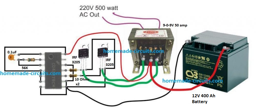
A basic 500 watt inverter with a square wave output can be as simple as above to build. However, to upgrade it with a battery charger we may have to employ a charger transformer rated appropriately as per the battery specifications.
Before learning the charger configuration let's first get acquainted with the battery specification required for this project.
From one of our previous post we know that the more appropriate charging and discharging rate of a lead acid battery should be at 0.1C rate or at a supply current that's 10 time less than the battery Ah rating. This implies that to get a minimum of 7 hours back up at 500 watt load, the battery Ah could be calculated in the following manner
Operational current required for a 500 watt load from a 12V battery will be 500 / 12 = 41 Amps approximately
This 41 amps needs to last for 7 hours, implies that the battery Ah must be = 41 x 7 = 287 Ah. However, in real life this will will need to be at least 350 Ah.
For a 24 V battery this may come down to 50% less at 200 Ah. This is exactly why a higher operational voltage is always advised as the wattage rating of the inverter gets on the higher side.
Using 24 V Battery
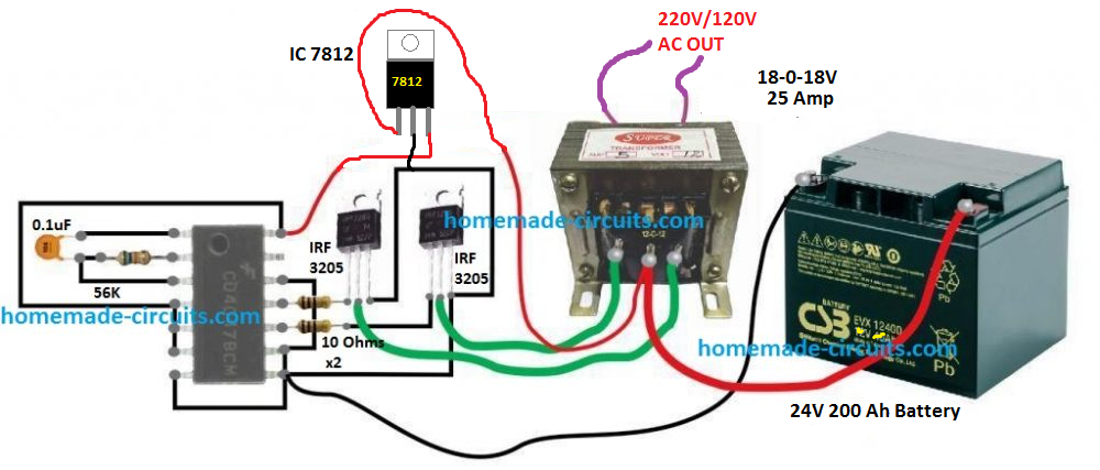
In order to keep the battery and the transformer size smaller and cables thinner, you may want to use a 24 V battery for operainf the proposed 500 watt design.
The basic design would remain as is, except a 7812 IC added to the IC 4047 circuit, as shown below:
Schematic Diagram
Battery Charger
To keep the design simple yet effective, I have avoided the use an automatic cut off for the battery charger here, and have also ensured a single common transformer is used for the inverter and the charger operations.
The complete circuit diagram for the proposed 500 watt inverter with battery charger can be seen below:
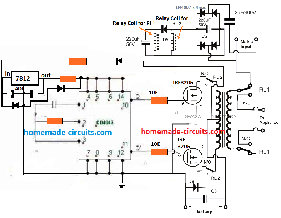
The same concept has been already elaborately discussed in one of the other related posts, which you can refer to for additional information.
Basically, the inverter uses the same transformer for charging the battery and for converting the battery power to 220 V AC output. The operation is implemented through a relay changeover network, that alternately changes the transformer winding to charging mode and inverter mode.
How it Works
When grid mains AC is not available, the relay contacts are positioned at their respective N/C points (normally closed). This connects the drains of the MOSFETs with the transformer primary, and the appliances or the load connect with the secondary of the transformer.
The unit gets into inverter mode and begins generating the required 220V AC or 120 V AC from the battery.
The relay coils are powered from a simple crude transformerless (capacitive) power supply circuit using a 2uF / 400V dropping capacitor.
The supply is not required to be stabilized or well regulated because the load is in the form of the relay coils which are quite heavy duty and will easily withstand the switch ON surge from the 2uF capacitor.
The coil for RL1 relay which controls the mains AC side of the transformer can be seen connected before a blocking diode, while the coil of RL2 which controls the MOSFET side is positioned after the diode and in parallel to a large capacitor.
This is intentionally done to create a small delay effect for RL2, or to ensure RL1 switches ON and OFF prior to RL2. This is for safety concerns, and to ensure that the MOSFETs are never subjected to the reverse charging supply whenever the relay moves from inverter mode to charging mode.
Safety Suggestions
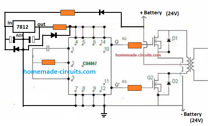
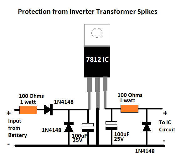
As we know, in any inverter circuit the transformer works like an heavy inductive load. When such a heavy inductive load is switched with a frequency, it's bound to generate a massive amount current spikes which may be potentially dangerous for the sensitive electronics and the involved ICs.
To ensure proper safety to the electronic stage, it may be important to modify the 7812 section in the following manner:
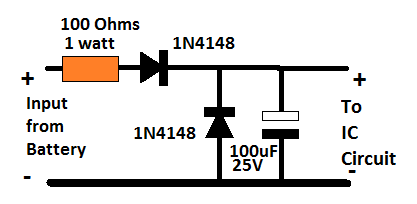
For a 12V application, you can reduce the above spike protection circuit to the following version:
Battery, MOSFET and Transformer Determine the Wattage
We have discussed this many times through different posts that it is the transformer, the battery, and the MOSFET ratings that actually decide how much power an inverter can produce.
We have already talked about the battery calculations in the previous paragraphs, now let's see how the transformer can be calculated for complementing the required power output.
It is actually very simple. Since the voltage is supposed to be 24 V, and power 500 watts, dividing 500 with 24 gives 20.83 amps. Meaning the transformer amp rating must be above 21 amps, preferably up to 25 amps.
However, since we are using the same transformer for both charging and inverter modes, we have to select the voltage in such a way that it suits both the operations optimally.
A 20-0-20 V for the primary side appears to be a good compromise, in fact it is the ideally suited rating for the overall working of the inverter across both the modes.
Since, only one half winding is used for charging the battery, the 20 V RMS rating of the transformer can be used for getting a 20 x 1.41 = 28.2 V peak Dc across the battery with the help of the associated filter capacitor connected across the battery terminals. This voltage will charge the battery at good rate and at the correct speed.
In the inverter mode, when the battery is at around 26 V, will allow the inverter output to be at 24/26 = 220 / Out
Out = 238 V
This looks a healthy output while th battery is optimally charged, and even when the battery drops to 23 V, the output can be expected to sustain a healthy 210V
Calculating MOSFET: MOSFETs basically work like switches that must not burn while switching rated amount of current, and also must not heat up due to increased resistance to switching currents.
To satisfy the above aspects, we have to make sure that the current handling capacity or the ID spec of the MOSFET is well over 25 amps for our 500 watt inverter. Also to prevent high dissipation and inefficient switching the MOSFET's RDSon spec must be as low as possible.
The device shown in the diagram is IRF3205, which has an ID of 110 amp and RDSon of 8 milliohms (0.008 Ohms), which actually looks quite impressive and perfectly suitable for this inverter project.
Parts List
To make the above 500 watt inverter with battery charger, you will need the following bill of materials:
- IC 4047 = 1
- Resistors
- 56K = 1
- 10 ohms = 2
- Capacitor 0.1uF = 1
- Capacitor 4700uF / 50 V = 1 (across the battery terminals)
- MOSFETs IRF3205 = 2
- Diode 20 amp = 1
- Heatsink for the MOSFETs = Large Finned Type
- Blocking Diode Across MOSFETs Drain/Source = 1N5402 (Please connect them across drain/source of each MOSFET for added protection against reverse EMF from the transformer primary. Cathode will go to the drain pin.
- Relay DPDT 40 amp = 2 nos
Upgrading to Modified Sinewave Inverter
The square wave version discussed above can be effectively converted into a modified sinewave 500 watt inverter circuit with much improved output waveform.
For this we use the age old IC 555 and IC 741 combination for manufacturing the intended sine waveform.
The complete circuit with battery charger is given below:
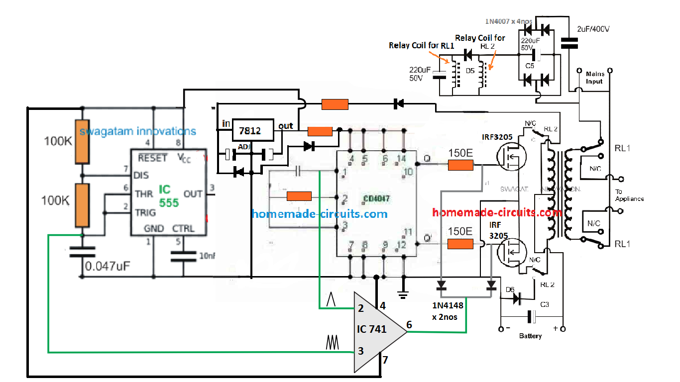
The idea is the same which has been applied in a few of the other sinewave inverter designs in this website. It is to chop the gate of the power MOSFETs with calculated SPWM so that a replicated high current SPWM is oscillated across the push pull winding of the transformer primary.
The IC 741 is used as a comparator which compares two triangle waves across its two inputs. The slow base triangle wave is acquired from the IC 4047 Ct pin, while the fast triangle wave is derived from an external IC 555 astable stage. The result is a calculated SPWM at pin6 of the IC 741. This SPWM is chopped at the gates of the power MOSFETs which is switching by the transformer at the same SPWM frequency.
This results in the secondary side with a pure sinewave output (after some filtration).
Full Bridge Design
The full bridge version for the above concept ca be built using the below given configuration:
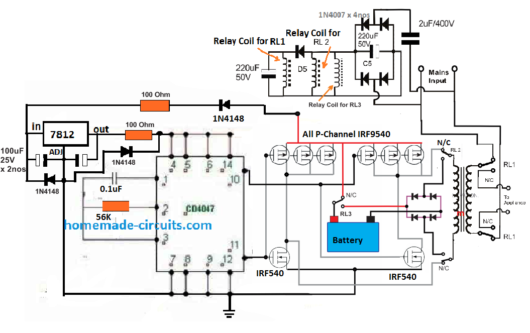
For sake simplicity, an automatic battery cut off is not included, so it is recommend to switched OFF the supply as soon as the battery voltage reaches the full charge level. Or alternatively you may add an appropriately filament bulb in series with the charging positive line of the battery, to ensure a safe charging for the battery.
If you have questions or doubts regarding the above concept, the comment box below is all yours.


Questions & Answers
I liked the circuit. I only wish it had a power supply for its regulation both in frequency and in output voltage. Thank you very much
Thank you, if possible I’ll try to update the details in the article.
Is 24v battery is available
Hi,I like the design. What can be done to the circuit so that I can use a two wire transformer at the primary side and also instead of using the relays I just use the same mosfets for inverter and battery charging? I’ll appreciate a schematic diagram if possible.
Hi, I’ll try to update it soon
Will appreciate
Hello sir swagatam,how did it go,did you find anything good for an update about an inverter circuit diagram using a transformer without centre tap?
Hi Evans, I have updated a full bridge version at the end of the post. You can check it out…
Sir pls upload current source inverter circuit and design configuration of it.
I will surely try…
Thank you sir for your kindness,now my other questions are;
1. Can we use N channel mosfets only with the same circuit,any update please? Coz with high currents, I will be forced to use a big number of p channel mosfets which Leeds to high cost and space limitations.
2. What could be the current ratings of RL 2 & RL 3 if for instance I built a 24vdc/220vac/6000w inverter?
Evans, N-channel cannot be used without specialized ICs or a bootstrapping network
Thank you sir for your response. So if I integrate a boostraping network then can use cd4047 as the oscillator? True or not? Any clarifications?
It is possible with bootstrapping introduced with any oscillator.
Sorry had a typing error,I meant cd4047
excellent design
I really appreciate this effort.
Am new in this website and am always looking forward to understanding how a smps circuit oscillates, cause am a 17yr old beginner in electronics
Thank you, I appreciate your interest…keep up the good work
I’ve been looking at various inverter circuit designs on the ‘net and youtube. You have done a very good job explaining your circuits and detailing how they work. As you know power inverters can be pricey for anything 500 watts and above, so your designs now seem obtainable to actually making my own.
What would be required to build a 2000w or 5000w power inverters? Does your circuit design change?
How would you go about calculating the components specs for a these higher wattage inverters?
Thank you for posting your circuits and your comprehensive yet well written explanation.
-Martin
Glad you liked it, I have explained the process of calculating the transformer and the MOSfET for upgrading the inverter to any desired power level.
can I have the layout in Pcb of the modified sine wave inverter circuit?
and what is the orange one in the circuit represents?
Hello Sir I have 7805ic and IRF 540 mosfet can I use it to make this inverter?
Bios, 7805 will not work, you will have to use 7812, IRF540 can be tried, it might work, but mount them on large heatsinks
Hi engineers,I have done this project is good,I even went further ahead by making it an automatic inverter charger. My problem is that my batteries don’t get charged fully since inverters with pwm usually have their transformer voltages halved or 2/3 of the same,any help on how I can improve the charging speed will be appreciated.
Thank you Evans, I have already addressed this issue in the article, under battery MOSFET, transformer selection….
hi sir, can you help me how to make a 500 watts inverter, 12v DC to 220v AC, 60H, and modified square waves? can you make a circuit for me and its layout on pcb?
Hi lloyd, you can try the following concept
https://www.homemade-circuits.com/1500-watt-pwm-sinewave-inverter-circuit/
good evening sir,i would like to know the formulas for calculating ic 4047 frequency
Yusuf, you can refer to this article:
https://www.homemade-circuits.com/ic-4047-datasheet-pinouts-application/
Hi
I need a protection circuit that will keep an appliance switched off during load shedding and only switch on when the power comes back on and is stable at 240v.
Kind regards.
Hi, you can try the concept presented in the following article
https://www.homemade-circuits.com/mains-high-low-voltage-protection/
Hi
Thanks for the reply appreciate it. Our line voltage is 240v and when we have load shedding it switches back on with over 300v. I need a circuit that will switch the appliances back on when the voltage stabilizes at 240v.
Regards
Hi, the linked circuit will do exactly that! It will never switch ON the appliance with the wrong voltage
I have request to you sir, pls upload configuration and design of current source inverter
Thank you Amar, I am studying it, and if possible I’ll post a related article soon.
Sir i have 3kw /400v Dc on-grid Solar system… when grid power switches off during peak hours of sunshine ongrid solar also switches off.. so energy from solar system getting wasted…so during this switched off time can we have another solar inverter without battery system to run atleast 2000w power system.. Night i don’t need power
Yes you can use the solar power by diverting it through a relay changeover. This relay should be powered from grid voltage, so while grid is available, the relay contacts keep the external inverter disconnected from the solar power. When the grid fails, the relay contacts switch over and connect the external inverter with the solar panel.
Thank you somuch for your Replay Sir.. without battery can i use solar energy directly .. just by converting to 220v AC from 3kw..400v DC
Hi K Gopi, yes that may be possible if the transformer is correctly designed for converting the 400 V into 220 V
Please I need answers because I wanna couple a 130w solar panel with 650VA UPS, will this work sir
Thank you so so much for your reply sir.. Have to finally get a jem in electronic field who solves the problems with efficiency..
You are welcome KGopi
Very clean and straight forward project i would like to design, But then how can i add an overload protection to practically work wit this project, Thanks Swagatam.
Thank you, you can add the following concept for overload protection:
https://www.homemade-circuits.com/low-battery-cut-off-and-overload/
swagatam sir i want 12v dc 1000w or 1200w power inverter ckt diagrams.
Sree, you can try any inverter design from this website, and upgrade it as per the details presented in this article:
https://www.homemade-circuits.com/upgrading-low-power-inverter-to-high/
Thanks for your good works. Can I add more 3205 mosfets for greater wattage? Thanks
yes you can, it is the MOSFETs, the battery and the transformer that decide the power output.
Hi Sir, It’s awesome explanation but I need to know, How we will come to know whether battery charged fully, Is there any led indication?
Thanks
Sidaray
Thanks Sidaray, the simplest way is to add an ammeter in series with the battery positive, when the needle nears the zero volt, it will indicate the battery is fully charged.