EMF pump circuits are devices which are popularly used for the purpose of identifying paranormal activities or entities by generating rapidly rotating magnetic fluxes in the ether. The conventional devices use a spinning magnet fixed over a motor spindle, however these are mechanical types and are prone to wear and tear.
Introduction
The explained circuit is a solid state version of the above, more reliable with its operations and very effective with the forbidden tasks.It is said that paranormal entities become more energetic in the presence of strong electromagnetic zones, especially when the magnetic fluxes are rapidly varying in nature.
The magnetic fluxes enriches the existence of a paranormal being such that its presence becomes aggravated and quickly traceable using ordinary equipment like RF detector or EMF sniffers.
The presence of the paranormal being enhanced in such a manner makes animals particularly very uneasy, especially animals like dogs would instantly get hyper under such conditions.
The circuit can prove to be an excellent EMF pump device for immediately tracking ghosts and other supernatural activities.
Circuit Operation
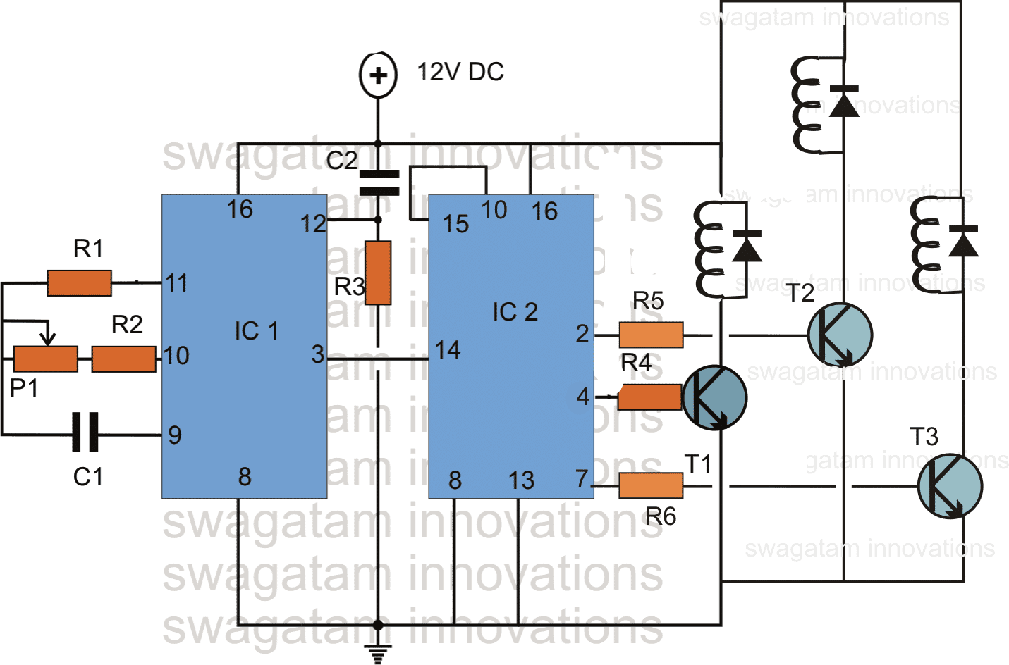
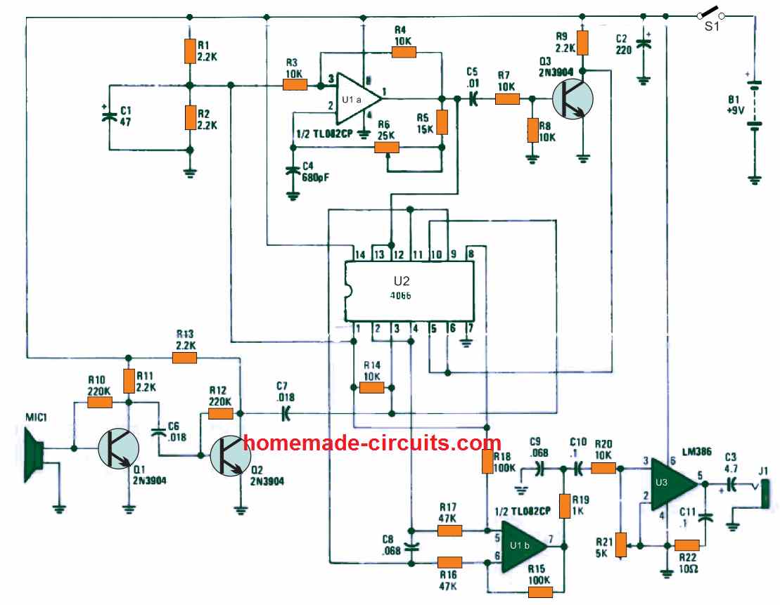
The figure shows a circuit design built around the versatile IC 4017 which is a divide by 10 Johnsons decade counter IC.
You can learn more about this IC and its pin outs in one of my earlier posts, comprehensively explained about its installations in a circuit.
Basically a clock pulse fed at the clock input of the IC activates its outputs to go "high" in a sequencing manner from the first to its last pin out in the order.
Using IC 4060 as the Oscillator
The oscillator IC 4060 is configured as a clock generator and supplies the required clocks to the IC 4017.
Here we have used only three of the outputs because only three electromagnets have been involved.
In response to the applied clock pulses, the output from the IC move sequentially across the three outputs rapidly, cycling around as long as the clocks are being fed.
The outputs are applied to power transistors which in turn are connected with strong electromagnet assemblies.
When the outputs of the IC sequence, the transistors also switch sequentially, triggering the electromagnets in a cyclic motion.
The rapid switching of the electromagnets in a rotational motion generates a high power magnetic influx sufficient to invite the "uninvited" in the zone.
The power to the unit should be preferably taken from a 12V 1AH battery source.
For tracking paranormal activities, you can use this circuit in conjunction with the ghost detector circuit explained in one of earlier posts, together the devices will produce pin point results.
Parts List
R1 = 2M2
R2 = 1K
R3 = 1M
R4, R4, R5 = 220 OHMS
P1 = 100 POT
C1 = 10uF/25V NON POLAR
C2 = 1uF
T1,T2,T3 = TIP122 (Should be Mounted On Large Heatsinks)
IC1 = 4060
IC2 = 4017
ELECTROMAGNETS ARE HAND MADE TYPES
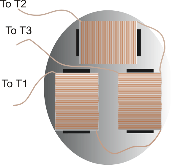
Electromagnet Fixing Details:
The three electromagnets should be fixed over a wooden board in the manner shown below, and the wires terminated to the relevant points of the assembled circuit.
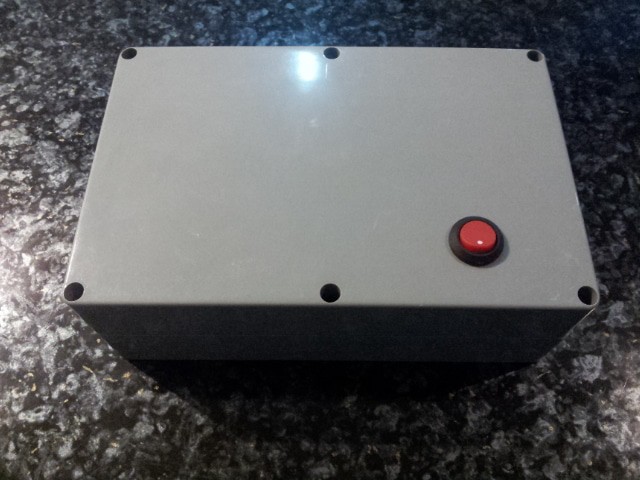
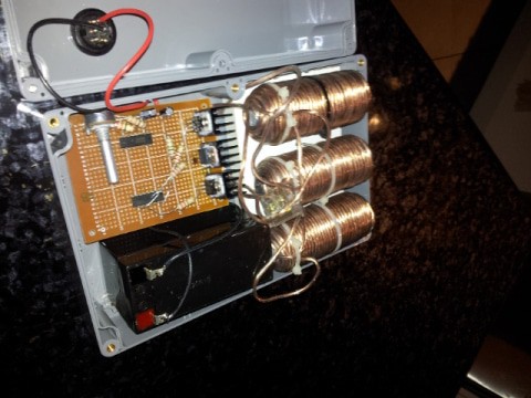
The following images of the built prototype were sent to me by one of the active readers of this blog, Mr. Dan.


Questions & Answers
I made this circuit board in Kicad along with one for a 10 magnent one if you would like it. They may not be perfect since I am still learning.
hey I’d like to build it send them plans to me.
That is great….glad you could build it. No problem if it is not perfect.
Can the battery be 12V 1.3 ah?
Yes, but it might get depleted very quickly.
Can there be more than 3 electromagnets used? And also could there be different resistors used to attempt different frequencies or would just changing the amount of turns per magnet slightly on each?
You can use upto 10 electromagnets stages across the 10 pinouts of the IC 4017 (3, 2, 4, 7, 10, 1, 5, 6, 9, 11).
Frequency cannot be changed for each electromagnet individually….the frequency will sequence across the above mentioned pinouts depending on the values of C1 and P1
Thank you very much appreciated
Greetings.
I have an idea for a new ghost hunting tool that I would like your help on. However, I do believe this device will be an absolute break-through device so I really do not want to put my idea out in the open for all to see and possibly take credit for. Kinda selfish I know.
Is there any way to message you in private for a quick discussion?
or could you email me at the attached email and please put breakthrough device in subject line.
I will be brief but I may ask of you to not disclose this idea if its not something your interested in doing.
To be up-front I am not asking for any monetary investment. If this idea does work and comes to bear fruit I will split all profits 50/50.
Thank you for your time.
R.W. Allen
Founder R.G.Paranormal Research Team
I truly appreciate your offer and your idea, and I trust it will be a breakthrough idea.
However, my sole intention of creating this blog is to share ideas among the folks, so if you are not willing to share the information then unfortunately I wouldn’t be able to participate in the discussion.
On this schematic it says c2 is 1uf but 1uf? 25v 50v is it a ceramic capacitor?
C2 must be non-polar 50V capacitor. You can use two 0.47uF/50V ceramic caps in parallel instead.
I realize that the answer may be simply “because, ghosts” but why three coils? Why alternate between the three coils? If ghosts are feeding off of EMF wouldn’t just plugging in one coil and leaving it on do the trick? I personally don’t believe in ghosts but I’m facinated by the concept and the ghost hunting gadgets.
The sequential EMF kind of produces more variation in the pumping effect and thus creates more attraction for the ghosts.
Ah, ty! I reread this and see now where you essential said just this. I also ended up looking up and learning more about magnetic flux. Now it makes sense, in a paranormal way, why varying fields would be able to transfer more energy to ghosts.
That’s right, thanks for the feedback!
Dear Swagatam.
Could you revert with electromagnets detail? wire type, core diameter, and how many turns?
thanks in advance.
Hi Nektarois, The electromagnet specs will depend on the frequency of the IC 555. I think around 100 turns of copper wire over any suitable iron core will be enough, with a 555 frequency of around 100 Hz
Dear Swagatam, have a good day,
Thanks a lot for your prompt reply.
Nektarios.
You are most welcome Nektarios
Need info on the coil winding, as well as wire guage.
Thank you
Coil resistance should be around 100 ohms
this is for the electromagnets correct? I’m making my magnets with 26 awg enameled copper wire and 100 ohms would take a lifetime to achieve… suggestion on what to use for core, wire gauge, etc.?
yes electromagnets. the core should be laminated iron as we have in transformers.
In the circuit of the emf pump there are 3 diodes in parallel at the inductors, which are not mentioned in the list of components. That diodes are? Thank you
you can use 1N4007
I'm trying to find a device or plans to build a device that will generate random EMF noise in the frequencies of 30 Hz – 100 Hz with an adjustable output of about 10 mG to 50 mG. The purpose is to disrupt the cellular oscillation caused by a constant 60 Hz high EMF in my house. Anyone have suggestions?
It can be done using a single 4060 IC, I'll try to present it in my blog soon.
thanks!
I'm trying to find a device or plans to build a device that will generate random EMF noise in the frequencies of 30 Hz – 100 Hz with an adjustable output of about 10 mG to 50 mG. The purpose is to disrupt the cellular oscillation caused by a constant 60 Hz high EMF in my house. Anyone have suggestions?
mosfets and BJTs are both like switches, capable of switching frequencies right from 1Hz to Mhzs, so the switching speed is not a concern here for both the counterparts.
The diodes placed across the coils will desaturate the coils as quickly as they saturate, so that it's always ready for the new pulse.
In the above design, Pi, R2 and C1 together and individually determine the frequency rate, you can tweak them to get any desired frequency as per your requirement.
mosfets are better than transistors no doubt, it can be used here for better efficiency, however transistors are also rated to work at much higher frequencies, so either will work, depends on what you have in hand.
You are correct, ferrite works better at higher frequencies than iron core which might become too become hot just like an induction heating