In this post we'll study a simple high current mosfet based SPDT DC relay, which can be used in place conventional bulky SPDT mechanical relays. The idea was requested by Mr. Abu-Hafss.
Working Concept
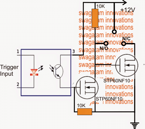
A simple high current SPDT solid state DC relay or a DC SSR can be constructed using a couple of mosfets and an optocoupler, as shown in the digaram above.
The idea looks self explanatory.
In an absence of an external trigger, the lower mosfet stays switched OFF allowing the upper mosfet to conduct through the 10k resistor connected across the positive and the gate of the mosfet.
This enables the N/C contact to get active, and a DC load connected across the supply positive and the N/C gets activated in this situation and vice versa.
Conversely in the presence of an input trigger, the mosfet connected with the opto emitter gets an opportunity to switch ON, switching OFF the upper mosfet.
In this situation a load connected between positive and N/O points gets activated or vice versa.
The Circuit Diagram
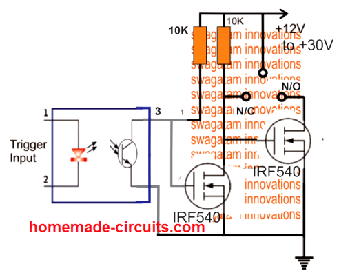
The above design can be configured in the following manner, and in fact this appears to be technically more correct, and therefore is the recommended one.
This design will work regardless of the opto input switching voltage, right from 3V to 30V DC.
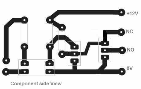
PCB Layout
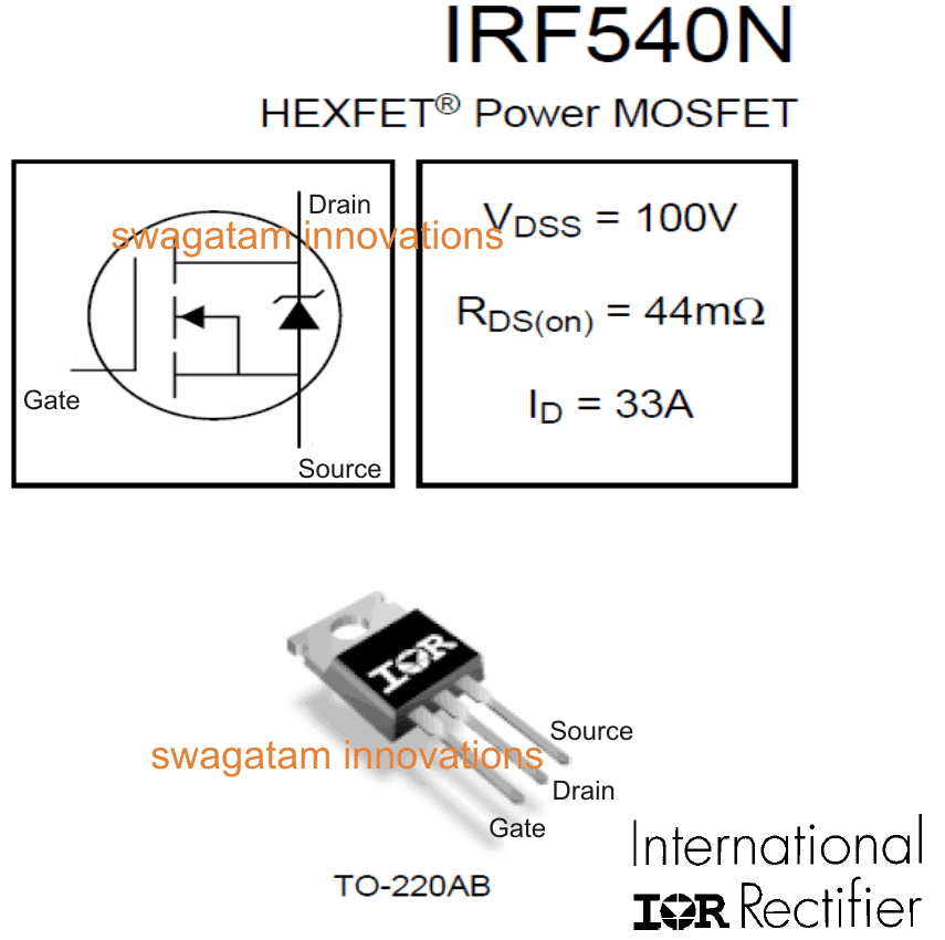
The following image shows the pinout details of the MOSFET IRF540, you can use any other MOSFET of your choice and as desired:
Upgrading the SPDT Relay to DPDT Version
Creating a DPDT version of the above DC solid state relay is actually not too difficult. We can do this by adding a couple of more MOSFETs as shown in the following illustration.
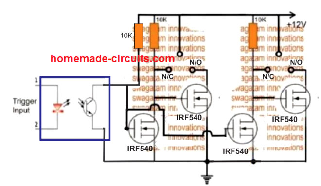
Here, although the poles appear to be a single pole, connected with the positive line, it could be simply separated and integrated with the different DC supplies for operating two individual loads, and implementing a DPDT SSR function.


Comments
Please Swagatam Majumdar please view this Circuit here
Now how can the SPDT circuit you post above be used to discharged the Capacitors?
Please view the main page where the circuit is and the accompanying explanations about it for you to understand it.
Remember the Circuit is an High Voltage of minimum of 120VDC after the bridge rectification.
So which MOSFET will be suitable at voltage input up to 240AS or VDC?
Thank you for your in-depth reply in view.
You can probably do it as given below:
Swagatam you said “Please ignore my previous comment..the diagram is actually correct, the NPN, PNP would conduct alternately.”
Do you mean I should connect the Base of the 2 transistor as you ealier drawn it?
If yes, do I still need the additional process of connect the driving transistor to ground?
What driving transistor will be best suitable?
NOTE: I am not a trained Electronic Engineer. So please do not be annoyed at me for my “cheap” questions.
Dare, do you want to switch the transistors through an oscillator stage? In that case you will have to connect the bases of the transistors to an oscillator stage such as IC 555 oscillator
This IC 555 circuit will need a separate 12 V DC for operating. The negative of this DC will need to be connected with the negative or the ground line of your free energy circuit.
I hope you have understood the configuration now!
The Negative of the Circuit is 2. One at the F.W.B.R and the other at the end of the terminal of the second capacitor to the left which connects to ground via the amp meter.
Which one am I suppose to connect to put of the 2?
Please explain.
The ammeter ground is the place where the external PWM negative should e connected.
Thank you for the quick response.
I could not see the transistors you recommended on for sale on aliexpress .
Could you please reveal other complementary transistors I can use?
You can try MJE340, MJE350. The negative of the pulse source at the transistor base must be connected in common with the circuits negative or ground line.
Sir, again thank you for the prompt reply.
But please, I do not understand what you mean by “The negative of the pulse source at the transistor base must be connected in common with the circuits negative or ground line”
Could you please draw the Circuit diagram of how to properly do that using the newly recommended MJEs? Please I beg you do that for me.
Thank you for your kindness.
Please ignore my previous comment..the diagram is actually correct, the NPN, PNP would conduct alternately.
Dare, the voltage pulse that you would use for triggering the transistor pair will need a low external DC source. The negative of this DC source must be connected with the negative line of the main circuit. Please refer to the datasheet of the transistor and identify the pinout details, and then you can connect them as indicated in the diagram.
…I think the diagram needs a correction, because the transistor needs to be triggered alternately and not together…I’ll try to update it soon…
Hi Swagatam. Not sure if you got my recent question so I’ll repeat.
I’m trying to use MOSFET’s to eliminate mechanical relays.
In this example the MOSFET gets extremely hot even though the load is only 3amps
http://www.dropbox.com/home/Public?preview=Problem+1.xlsx
In this second example, when the TV is switched on it’s ok with mains power but when on battery power, the 12v dips to 9v and the converter output goes haywire. Initially by mistake I had the S & D of the MOSFET reversed and it switched between AC and battery fine – it just wouldn’t switch off!
http://www.dropbox.com/home/Public?preview=Problem+2.xlsx
I would be very grateful for any help or suggestions
Thanks
Paul
Hi Paul,
I have changed the design layout at the input side, you can find it in the second and the third diagrams. Please modify your circuit accordingly. If still it doesn’t work then probably your MOSFETs might have gone bad.
The dropbox site is asking me to register so I couldn’t view the diagrams.
Tks so much – I’ll try that. This link should work ok
http://www.dropbox.com/sh/us8dugcmb8971f3/AACSYvVBiWG8fmwgd6d-Jgpza?dl=0
Paul
Sorry, it’s difficult to understand because it’s not drawn in the conventional manner with proper MOSFET symbols and markings.
I do apologize! Trying to draw up something in excel doesn’t always work so well.
I’ve modified Problem 2 as follows
http://www.dropbox.com/s/8o24e6pd1guydog/problem%202.xlsx?dl=0
I hope this is more readable.
This is the one I really want sorted out if possible
If I short D & S together then the switchover from mains to battery and back again works perfectly. I just can’t then switch it off!
Many thanks for your patience
Paul
Sorry I should have explained. The switch S1 is a remote microswitch which cannot take high current hence the need for a local switching device.
The MOSFET is IRF740 (n-channel).
The IRF740 is a 400V device which may not be compatible with a 12V supply, I would recommend trying an IRF540 instead and see the results.
The MOSFET is there in place of a mechanical relay to switch the system on and off.
I think I had resistor R1 wrongly connected to +12v instead of GND (now corrected). It still goes haywire.
Paul
But there’s already a switch in the form of S1 to turn the system ON OFF If I am not mistaken. May be I am missing something in the design.
And what is value of the MOSFET, is it as per the input supply specs?
What is the role of the MOSFET in the design, since it’s always ON?
Yes, you must remove the MOSFET and connect the D/S link directly, so that the diodes solely can handle the changeover.
Hello,
Please how to add anti backfeed protection like your “Ideal Diode” circuit?
Thanks,
Nacho
hey again Swagatam
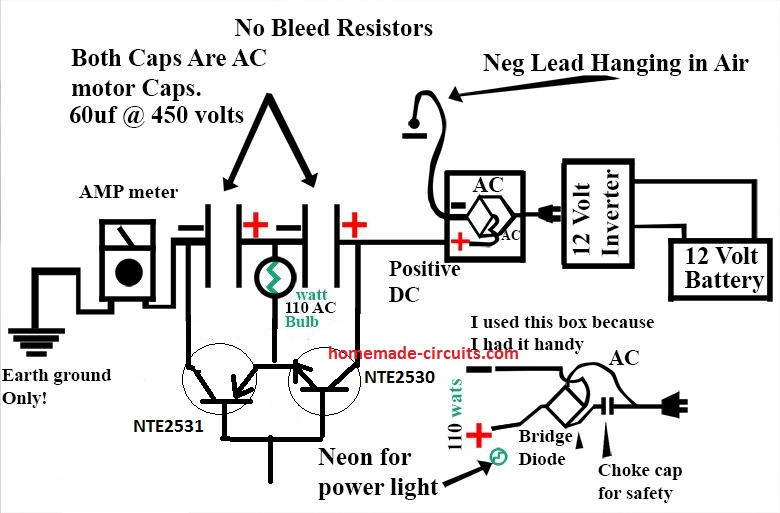
I did a quick drawing on tour fist picture on this page to help you understand better of what problem i am facing:-
link to the file: https://ibb.co/NFHJb6r
you can see I am working on reconfiguration of PV panels so that when I turn on one mosfet the above PV panel connects to any one of the below two panels as required.
the thing is…
Vgs should be greater than threshold right but in my case the PV panels are going to hinder the Vs which is not ground for me
so is there a way an IC that I can use to control the gate without having the source potential problem
thank you
You can probably also try this:
https://www.homemade-circuits.com/wp-content/uploads/2019/08/PV-reconfiguration.png
Thanks Trex, Got it!
I think you can probably try the following full bridge concept:
https://www.homemade-circuits.com/wp-content/uploads/2018/12/IR2110-3.png
The upper panel could be connected at the center between the OUT/OUT terminals.
The other two panels could be connected in series with the drains of the upper MOSFETs.
The HIN/LIN inputs then could be flipped with opposite voltages for toggling the center panel with one of the upper panels.
Hope it makes sense!
hey Swagatam
I am doing a project related to PV array dynamic reconfiguration based of partial shading concept.I wanted to use this (SPDT) and connect one PV panel with another when I want to. Currently this only gives me liberty to connect one PV panel with 2 others(SPDT)
Can you suggest a way for increasing the double throw method with less mosfets or a general way to help me with this project would be good too.
Hey Trex, for isolated double throw two more MOSFETs would be required, without adding MOSFETs a DPDT feature may not be possible.
Hi Swagatam,
Thanks for so amazing solution thet helps me a lot with current solar/wind powered projects.
Would you please provide a similar solution for (DC) SP3T, SP4T.. SP*T Mosfets switch?
Best,
Hi Nacho, I am glad my articles are helping you. For getting SP3T, SP4T etc, you just have to add that many MOSFeTs in parallel with the existing pair.
For example, for a SP3T, we would want 3 more N/C N/O points, which could be achieved by adding 3 more MOSFET pairs in parallel. I hope you got it!
any schematic that you made for a SP3T?
I have updated a DPDT version as an example, the idea can be further upgraded in an identical for getting SP3T also….
I checked it, it looks too lengthy, so it can take many hours to get it sorted. A block diagram instead would be more suitable and easy to understand, or a written description step wise would also do.
Could you upload it on any free image hosting site and give me the link? then I can check it out.
Or you may simply explain it verbally so that configure the schematic myself
Thanks so much for help. I now need to do some testing to see how this works out.
My next problem is eliminate 2 relays.
1. When 12v switches on I need to direct 12v load (up to 10amp) to the rest of the devices.
2. When 12v switches on I need to switch on the AC mains (250v) at 2amp
Because this system includes a pa amplifier I need to be careful about interference
So looking at various transistors and triacs has left me floundering.
Please help!
Paul
Just to be sure, is this 12V from the battery and solar panel? For all these arrangements we might need a slightly more complex circuitry.
The interference from the diodes can be avoided by adding 1000uF capacitor across the common cathodes and ground.
If you can provide the complete scenario point-wise I may try to figure it out through a schematic.
Really? That’s fantastic. Is there a danger of the two sources oscillating between the two if the voltages are close (say 0.3v difference) because I don’t think the TV will work at 18.5v
Paul
Yes it may oscillate if both the sources are at close levels. You can add a 19V volt regulator between the TV and diodes, this will ensure that the TV always gets 19V regardless of the source
Wow! This sounds too easy. The 12v solar battery also runs a sound console and some led lights so the buck converter is on all the time. If this converter and the mains power supply (smps) are both on and connected in parallel (with protective diodes) which one will the TV draw current from?
Thanks Paul
It will depend which source has a slightly more voltage. If the SMPS has 1V higher than the buck output then the TV will draw from the SMPS and vice versa. So basically the diodes work like silent switches and allows only the source which has higher voltage for the load.
Hi Swagatam
I scratching my head to see if your spdt circuit will work for me.
I have a TV which requires 19.5v DC.
If AC power is on then it gets 19.5v from a mains power supply.
When AC fails then it needs to switch over to a solar battery backup with a 12v to 19.5v step-up converter.
When AC returns then it needs to switch back after a short delay to allow the power supply to come up to speed.
Help appreciated, thanks
Paul
Hi Paul,
No need of using this complex circuit. You can feed the positives from the solar controller and the AC adapter through separate diodes and connect the common cathode ends with the TV positive terminal. The negatives can be all joined into common. However for getting a delayed response from your adapter you may have to add an additional delay timer at the cathode side of the adapter diode. Hope this helps!
Hi Swagatam,
I would like to do something similar, but maybe you can help me how to do it.
I have many 4.2V ION cells in series and would like to either couple the cell in or bypass the cell.
I would like to control each cell by a MCU (Arduino Mega) and select if the cell needs to be i serial with the other cells, or needs to be bypassed.
Thanks for your work, really appreciate it.
Thank you Peter,
However Arduino is not within the range of my expertise so it can be difficult for me to program it for you, if it’s without Arduino then may be I can help!
I was only the analog MOSFET circuit i would like you help with. Actually it’s a OPTO isolated MOSFET SPDT switch, good for 20A, i would like help with.
you could probably try the following idea:
https://www.homemade-circuits.com/wp-content/uploads/2018/08/series-Li-ion.png
only one transistor can be ON at a time.
Very nice tutorial.
I would like know how many current this circuit can flow with it mosfet of schematic?
Thank you, however I am not sure regarding the specs of the shown mosfets, please refer to the datasheet for the answer, or you can replace the same with any other known n-channel mofet.
Thank you for your quick answer. I’m admiring your work.
I have a doubt maybe you could tell me about MOSFET. how transistor BJT have a drop voltage fixe or nearly 0,7V, i would like know if mosfet, have a drop voltage fixe how transistor BJT of 0,7V? Or only drop voltage MOSFET is calculed on your RdsOn?
I am createing a system of backup energy with battery for my circuit, when supply power main is cut, my battery begin work, I am use battery lipo 3.7V and doing a step-up for 5V just when power main is cut. when main power is cut, i have MOSFET P that begin work, flowing current for my circuit main again. I cant to lost nothing voltage when this mosfet switch. In my simulator everything work normaly, but still do not a real circuit for test, maybe your experience can anwser my doubt about mosfet have some lost voltage how transistor
thanks
Vinicius,
0.6V is the BJTs base triggering voltage, for mosfets it is over 6V,… ideally 10V.
you can try the concept which is shown in the following article, and check the response
https://www.homemade-circuits.com/2014/12/12v-dc-solid-state-relay-ssr-100-amps.html
Can i simply duplicate the whole circuit for a DPDT? THX!
yes that can be done.
Great circuit! But, why is the optocoupler needed? Why can’t control the switches directly from the trigger input? thx!
yes opto coupler can be avoided and the input directly connected with the trigger point, an opto may be used only if the trigger source needs to be isolated from the relay
Very nicely written. Thanks for your precious work. One question though. In absence of an external trigger, what is the input at gate for the lower MOSFET? SHould it be connected to ground or to a supply voltage?
Thanks!
I am glad you liked it, the mosfet gate of the lower mosfet is connected to ground via a 10K resistor.
Hello sir thank you for this circuit now I can implement the over load protection circuit,relay have being my problem. Please may I ask.Q1 to achieve high amps I just need to use high amp mosfet.eg to handle 200amps I use like irfp2907 right? Q2 will the mosfets need heat sink as I plan to use it for up to 150amps inverter.Q3 how do I modify it to handle higher volts , say 24-48 volts. Q4 if I use 4 mosfet to make it DPDT will it work. Can the optocoupler handle it? Q5 what will be the recommended mosfet gate volts .Lastly Q6 what will be the trigger volts. Also is it ac or dc? I look forward to your reply is very important to me . Am Shedrach proudly your Student.
Hello Sherach, here are the answers:
1) yes you just need to upgrade the mosfet current (or voltage) specs for achieving higher wattage at the output
2) heatsink will be strictly required, may be with fan cooling also.
3)For higher voltage make sure the mosfets are rated above that limit…for 48V it should 60V and so on.
4) 4 mosfets can be used for getting DPDT operations.
5) 10V minimum and 15V max
6) the trigger voltage can eb anywhere from 2V to 15V but make sure to add a roughly calculated limiting resistor in series accordingly for safeguarding the opto LED.
Hey!
Amazing work! Wanted to know how do i modify the circuit to switch 230v AC?
it's done, here's the link:
https://www.homemade-circuits.com/2016/07/triac-spdt-relay-circuit.html
Thanks a lot! Looking forward to it. 🙂
thanks cypher, that's a good suggestion I'll try to post it soon in this website.
I am currently using an automotive SPDT relay to simply switch a 0 ohm ground signal that my cruise control unit is looking for. This is the trigger that shuts the cruise control off when you tap the brake pedal.
I am currently using a relay and it works fine but that the relay is loud and click every time I tap the brake pedal drives me crazy. I see in your above diagram and write-up you use the word "load" for both the N/C and N/O terminals so that tells me this design would work for situations where the relay is being used to switch circuits drawing current. My question is whether or not the same circuit can be used for a near-zero load (ground signal wire switching) or if I'd need to stick with something like the mechanical relay to accomplish this?
You can effectively use the above solid state relay as long as the "load" current rating does not exceed the current specs of the mosfets, as long as this is maintained the circuit would serve the purpose well….however the above SSR will require a positive signal for activation, a ground signal will not work with the above design.
Tested and working! Thanks a lot Swagatam..
My pleasure Vasilis! keep up the good work
Hi Swagatam, nice to see that there are people like you in this world. And, more, thanks for your precious work.
It should be interesting to publish an DPDT SSR…it shouldn't be so different from an SPDT: in the end a DPDT is a twin-SPDT!
In addition, it could be interesting to evaluate the possibility to add the optional "stepper" characteristic (at first pulse, the switch takes place and remains unchanged until a next pulse will be issued, see "stepping relay" on Wikipedia).
What I'm talking about is a full conversion of a mechanical "Form C" contact (break-before-make) DPDT into a perfect Solid-State equivalent, with 6 (3+3 independent each other) switching contacts (of which power & voltage can be easily adjusted by changing the components's values) plus the 2 low-voltage terminals to which apply the voltage needed to operate the switch.
There are already, on the market, devices like the one proposed but these are very expensive and often unavailable for tailor-made needs so it will be very useful for many people to learn how to build one by ourselves.
Many thanks in advance.
Fabrizio, Rome – Italy (fabrizioricciarelli@gmail.com)
Thank you so much Fabrizio,
The first two specifications that you have mentioned looks feasible to me and could be designed.
However I am not so sure about the "form C" counterpart specs, I'll try to investigate it though, and see whether or not I am able to transform it into the solid state version.
I'll try to include the idea in my blog, possibly soon.
I want to use relay to on & off motor as per level of water tank.current 10-12 amp.
10amp 120vac or 10 230 vac which relay use?
bc547 or sl100 ehich transistr use
Hi swagatam
i want to use relay for on & off motor as per water level in tank .
current approx.10-12 amp.
so 10amp 230 vac,10 amp120 vac,which relay use ?
transistor bc547 or sl 100 which is suitable?
plaese reply me.
Hi Rahul, BC547 will do, make sure the coil current is not rated above 60mA
very nice